1. adeveza :1PCB
2. apnneto :1PCB
3. goldkenn: 3 PCB
4. AR2: 2 PCB
5. Brooksl2: 1PCB
6. mvictor69: 1PCB
7. jonwhitear: 1PCB
8. rredline : 1PCB
9.aradan 2x sets of dac and psu
10.vasillis 2x dac+ psu
11. Ardahan: 1 PCB
12. frankwilker: 1 PCB
13. goldkenn : 3 PCB
.....
thanks
ypu list double
Hi,
This is my first post on this forum, but "beginnings are the hardest 🙂".
For me 1 PCB + 1 PSU
Is it possible to use this stuff as a phonostage ( I need MC ) ?
This is my first post on this forum, but "beginnings are the hardest 🙂".
For me 1 PCB + 1 PSU
Is it possible to use this stuff as a phonostage ( I need MC ) ?
Hi,
This is my first post on this forum, but "beginnings are the hardest 🙂".
For me 1 PCB + 1 PSU
Is it possible to use this stuff as a phonostage ( I need MC ) ?
yes, if your phone USE hv , from 150V to 400V
thanks
One board please Quanghao.
1. adeveza :1PCB
2. apnneto :1PCB
3. goldkenn: 3 PCB
4. AR2: 2 PCB
5. Brooksl2: 1PCB
6. mvictor69: 1PCB
7. jonwhitear: 1PCB
8. rredline : 1PCB
9.aradan 2x sets of dac and psu
10.vasillis 2x dac+ psu
11. Ardahan: 1 PCB
12. frankwilker: 1 PCB
13. goldkenn : 3 PCB
14. passive420: 1 PCB
(21 boards)
Thanks
Hi passive420!
i was make PCB yesterday! later 2 week we will have all!
thanks
Quanghao,
did you change your design to incorporate Jean-Paul's suggestions? They really make sense and would improve quality of your boards and users safety.
Thanks
AR2
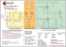
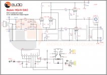
Complete schematic HQ-IV tube banlance DAC
I spent a lot of time to test multiple value capacitor, resistor for design. Finally I chose was the best plan.
And here is the complete schematic.
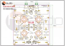
I also did a lot of PCB testing, and this is my favorite PCB.
quanghao
Thanks
I spent a lot of time to test multiple value capacitor, resistor for design. Finally I chose was the best plan.
And here is the complete schematic.
I also did a lot of PCB testing, and this is my favorite PCB.
quanghao
Thanks
Attachments
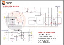
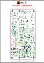
Complete schematic No.shunt HV supply
Complete schematic No.shunt HV supply
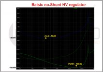
No.Shunt HV regulator
V-in: Max: 450V
V-out: 150V to 420V
Current load max: 100mA
PSRR: -180dB
Z-out: 0.03mOhm
and more information with GR: http://www.diyaudio.com/forums/group-buys/287234-no-shunt-hv-regulator.html#post4623555
Complete schematic No.shunt HV supply
No.Shunt HV regulator
V-in: Max: 450V
V-out: 150V to 420V
Current load max: 100mA
PSRR: -180dB
Z-out: 0.03mOhm
and more information with GR: http://www.diyaudio.com/forums/group-buys/287234-no-shunt-hv-regulator.html#post4623555
Attachments
Last edited:
If you change the regulator to an Ultra Low Drop version you can use 6V transformers and have no exceptional dissipation and it allows for use of standard 6V transformers (or 6.3V windings on "tube transformers" with combined HV and LV windings ). With LT1084 you will need higher AC voltages than 6V. So your design choice limits the design. Please do the math and design for use of 6V transformers. They are more easily available contrary to 7 or 8V transformers. Many will choose a 9V type as that is a standard value too and then dissipation will be unnecessarily higher.
Thank you for the muting relay. I am sure the builders will like this.
Thank you for the muting relay. I am sure the builders will like this.
Last edited:
Thank your advance
I use Lt1084 , so use for many tube can use, and with 12VAC for many tube can use!
Thanks again
I use Lt1084 , so use for many tube can use, and with 12VAC for many tube can use!
Thanks again
So you leave it up to the builders to use a 12V transformer ? OK. Making it versatile is nice but leaving it to the imagination of the builders is somewhat of a risk. Not all are that gifted to correctly understand such matters and just want to follow a BOM blindly. Some will use that 12V transformer with the LT1084 adjusted for 6.3V which will lead to the reg glowing more than the tubes 😀....Things can be too versatile 😉 As indicated you omit the possibility of guys re-using transformers that are meant to be used with tubes that have 6.3V windings !
Why not choose 2 footprints: one that allows for 12V regulators and one and one for a 6V ultra low drop LDO ? Just add some extra lines in the BOM:
- Parts necessary for 12V filaments (tube types X,Y and Z)
- Parts necessary for 6.3V filaments (tube types A,B and C)
Or keep it simple and choose an ultra low drop reg for use with both 12V and 6V filaments and adjust transformer voltage, cap voltages and setting resistors accordingly in the BOM. I don't want to be too critical but some minutes extra thought and your design will be usable both with standard 6V transformers and special tube transformers with standardized windings for filament use. I think many will appreciate that as it prevents the need for 2 separate transformers and it allows for reuse of transformers that have more windings. Not possible with LT1084 !
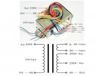
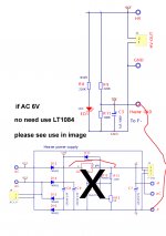
Maybe my words are unclear, if any of the guys reading this think so please explain it in better words. A simple choice can lead to way better execution of filament power and more choice in usable transfomators. Please see the attached picture (a bad example with 220V primaries, no current indication and of questionable quality but you'll know what I mean).
Why not choose 2 footprints: one that allows for 12V regulators and one and one for a 6V ultra low drop LDO ? Just add some extra lines in the BOM:
- Parts necessary for 12V filaments (tube types X,Y and Z)
- Parts necessary for 6.3V filaments (tube types A,B and C)
Or keep it simple and choose an ultra low drop reg for use with both 12V and 6V filaments and adjust transformer voltage, cap voltages and setting resistors accordingly in the BOM. I don't want to be too critical but some minutes extra thought and your design will be usable both with standard 6V transformers and special tube transformers with standardized windings for filament use. I think many will appreciate that as it prevents the need for 2 separate transformers and it allows for reuse of transformers that have more windings. Not possible with LT1084 !
Maybe my words are unclear, if any of the guys reading this think so please explain it in better words. A simple choice can lead to way better execution of filament power and more choice in usable transfomators. Please see the attached picture (a bad example with 220V primaries, no current indication and of questionable quality but you'll know what I mean).
Attachments
Last edited:
Hi jean-paul!
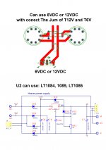
i was not you low LOD low drop voltage, but in this can use
LT1085, Lt1086 with low current tube heater, ex: 12AU7 x 4.
and the DC in , use can use 6vDC or 12vDC, so it is simple, only use Jum in the
PCB. you can connect them in parallel or serial
please see my image!
thanks
i was not you low LOD low drop voltage, but in this can use
LT1085, Lt1086 with low current tube heater, ex: 12AU7 x 4.
and the DC in , use can use 6vDC or 12vDC, so it is simple, only use Jum in the
PCB. you can connect them in parallel or serial
please see my image!
thanks
Attachments
Yeah I just tested with a generic LT1086 PSU board I have with a 10 Ohm load (so 0.63A) and things work out just barely OK with regards to minimum input voltage and ripple voltage. Board has Schottky diodes and a 4700 uF cap but it works with a 230 V to 6V transformer putting out 6.7 V under load. Now imagine higher load and a transformer putting out 6.1V....
* I am not so sure how things will be with 4 tubes at 6.3V as current will be 1.2A. My guess for now is that the PSU will need more capacitance than 2 x 2200 uF to keep ripple low enough for the LT1084 reg to work OK. I found this excellent page when googling for the datasheet of LT1084. Maybe you can recalculate your design with given examples:
http://www.pmillett.com/dc_filament_supply.htm
Reason for my advice to use lower drop regs is that I recently needed to design a PSU for 5V filaments with a 5V winding. Things become quite tight in that case 🙂 Transformer choice is suddenly less generic with such low voltages. That's what I learned anyway.
Last edited:
Please use a few more filter caps or larger value caps as you will definitely need lower ripple voltage anyway with LT1084 and 6V transformers. Add LT1764 to that and your worries will be over ! Using LT1764 with its 0.34V dropout will ensure most 6V transformers suitable to be used for 4 tubes at 6.3V/1.2A load. Only do this when you want just the tubes to be hot and don't want to waste power with no reason i.e. green design/better reliability design.
Not many will want to use an external PSU for filament DC power when the board has one onboard.
Not many will want to use an external PSU for filament DC power when the board has one onboard.
Last edited:
Hi jean-paul!
tyou should remember that it is very important transformer. It greatly affects the sound output.
If it does not enough current for filament tube, will cause huge buzzing ( hum big )
I see your transformer is is small ( may be im wrong ) -thanks
you need a good transformer, it is more important than my PCB.
And you should invest it better is to try to use the transformer of other projects!
thank you.
You are not listening but you don't need to. I just present a solution that works. Did you even calculate the filament PSU ? I don't think so. It will not work with transformers that are mostly used. It will work with 12V transformers and high dissipation. The PSU I tested was just to show the fault in the design.
In most simple words:
- your board needs more capacitance ( C8 and C9 must be larger)
- 6V transformers can not be used with 6.3V filament tubes the way things are now
In most simple words:
- your board needs more capacitance ( C8 and C9 must be larger)
- 6V transformers can not be used with 6.3V filament tubes the way things are now
Last edited:
You are not listening but you don't need to. I just present a solution that works.
ok, i see you now !
so what you advance more ?
thanks
Please use a few more filter caps or larger value caps as you will definitely need lower ripple voltage anyway with LT1084 and 6V transformers. Add LT1764 to that and your worries will be over ! Using LT1764 with its 0.34V dropout will ensure most 6V transformers suitable to be used for 4 tubes at 6.3V/1.2A load. Only do this when you want just the tubes to be hot and don't want to waste power with no reason i.e. green design/better reliability design.
Not many will want to use an external PSU for filament DC power when the board has one onboard.
LT1764 is good, so a liter change in the PCB, thanks
- Status
- Not open for further replies.
- Home
- Group Buys
- HQ-IV tube output balance DAC