I would use on JFET and one PNP transistor, in kind of Sziklai pair, it is the best that I ever tried. ;-)
Feedback divider from collector to ground, it is also the load for PNP transistor. Source of JFET goes to the lower resistor in the divider. Minimum noises compared to your "classic" schematic.
Feedback divider from collector to ground, it is also the load for PNP transistor. Source of JFET goes to the lower resistor in the divider. Minimum noises compared to your "classic" schematic.
Member
Joined 2009
Paid Member
can you sketch what you are describing - sounds interesting !
I know Hugh uses CFP in some of his hybrid designs. I've found the CFP to sound 'harsh' except when used in the output stage but I've never tried it as a driver for tubes.
I know Hugh uses CFP in some of his hybrid designs. I've found the CFP to sound 'harsh' except when used in the output stage but I've never tried it as a driver for tubes.
Member
Joined 2009
Paid Member
What would be the primary Z for a 70V line tranny used as OPT?
I remember thinking that the PE version that I used was about 3500 ohms, but I don't remember if I had an 8 ohm load on the 8 ohm tap, or the 4 ohm tap. The guitar amp I made sounds good, but different depending on which tap I connect my 4 ohm speakers to. Volume is about the same either way. I will have to measure one next time I get a chance.
Every 70v transformer will be different depending on the power levels of the different taps. Depending on these taps, there might not be a valid center tap. I know that the larger (15 watt?) PE unit does not have a CT, and does not work well as an OPT.
Yes, that's the one I have some samples of. Seems like a nice valve.
Yes, I've liked it very much in the one circuit I've used it in.
As i understand it, it was used in the audio output stages of televisions and radios in addition to being a good driver tube for bigger tubes.
I have several here and I think it would be pretty neat to use in a small PP build for near-field listening.
OPT impedance, from what i have been able to glean, should be 10-12k with b+ at 300v or so.
Member
Joined 2009
Paid Member
Thanks, that's useful information, I have no prior experience with PP hollow-state and was going to start looking at what kind of impedance was wanted. I was leaning in the direction of 10k but you've strengthened my confidence in this choice.
See attached diagram. I tried translating the russian text and was disappointed to find that it describes the OPT in terms of how to construct it. Core, bobbin, gauge of wire, etc. Except for the notation that the secondary has an impedance of 13 ohms.
But the general ideas are sound, I guess. There are a few 6n6p p-p designs out there. You could also search for 6h30pi designs, iirc it's in the same family.
6n2p is of course a soviet 12ax7.
But the general ideas are sound, I guess. There are a few 6n6p p-p designs out there. You could also search for 6h30pi designs, iirc it's in the same family.
6n2p is of course a soviet 12ax7.
Attachments

Last edited:
What would be the primary Z for a 70V line tranny used as OPT?
70.7 is the square root of 5000, so a 1W primary is 5K ohms, the 2W tap is 2.5K, etc. Understand that the center tap is at 1/4 Z. So, ferinstance, the 20W tap is in the center of a 5W primary, which has end-to-end Z of 1K and end-to-CT Z of 250R.
I'm thinking about how I want to drive the output tubes. I'd like some help to evaluate some hybrid options - using some SS parts.
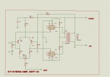
Well, if you want to keep things really simple, then this approach makes a lot of sense:
Attachments
Member
Joined 2009
Paid Member
Member
Joined 2009
Paid Member
Does anybody have comment on the ARC Classic 30 design ? - why they chose their approach. They have a two-device inverter up front, then a JFET based cross-coupled phase splitter to some driver triodes - it all looks very complicated. Can a simple CCS loaded LTP be a better approach (sonicaly) ?
The ARC schematic is attached. I re-drew the inverter to make it easier for me to 'see it' and posted that previously in this thread. There are good reviews of this amp which is why it has my interest.
I know a small cheap OPT is not an option with cathode feedback, but it is the front end of the amp design they have that I'm looking at now.
Attachments
I think they found a source toroid transformers, so decided to add some balancing opamp. Speaking of an input, it resembles Audio Research, where they inverted "phase" by a tube inverter stage with parallel feedback. I do not know, probably it come from so called "Transformer-less balanced input" where the fashion is to use an opamp to invert the "phase". They selected currents for driver tubes higher than could be delivered by JFETs they had in their bin, so they decided to parallel them.
Of course, I am guessing. 😀
Of course, I am guessing. 😀
They are using balanced feedback from the OPT secondary, returned to the sources of Q3 and Q4. This requires that Q3 and Q4 be driven by a balanced signal. That is why they have the inverter driving Q4, with Q3 being driven directly from the input.
Member
Joined 2009
Paid Member
ah, good point.
I'm also seeing that an LTP based phase-inverter does best with a -ve supply whereas the Paraphase inverter ARC uses doesn't. I'm looking for small and simple so this additional bias supply may be something to avoid - suggesting auto-bias for the output tubes instead of fixed bias.
I'm also seeing that an LTP based phase-inverter does best with a -ve supply whereas the Paraphase inverter ARC uses doesn't. I'm looking for small and simple so this additional bias supply may be something to avoid - suggesting auto-bias for the output tubes instead of fixed bias.
If you want simple I would go for something like ericj posted here
Use a 12AX7 and ECC99, though you may need to change the input tube based on how much gain you need. Maybe use a 12DW7 to drop the output impedance of the phase splitter as it needs to drive some capacitance. You need to get the parameters of the OPT you are going to use and simulate that circuit to determine proper compensation and coupling capacitor values. You would need a heavily filtered (or even regulated) B+ since the low plate resistance of the ECC99 makes it susceptible to B+ ripple intermodulating with the signal.
Another alternative is using two 6BM8/ECL82 in PP in pentode mode, with the two triodes as a paraphase splitter. Or you could use them as a LTP with a CCS in the tail that you could tie to a negative voltage derived by rectifying the heater winding.
Member
Joined 2009
Paid Member
You would need a heavily filtered (or even regulated) B+ since the low plate resistance of the ECC99 makes it susceptible to B+ ripple intermodulating with the signal.
How about this solution to the B+ problem ?
More Aikido Active-Tail Phase Splitters
I haven't seen anybody actually use this approach. And when you modulate the tail of an LTP you create a Mixer, not sure if this is going to work ?
Attachments
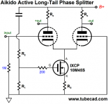
That's probably not a bad idea, though I was talking about ripple affecting the output stage not the phase inverter. However I would be concerned about the low drain-source voltage resulting in variable capacitance that could introduce excessive distortion at high frequencies. Not sure, I never played with that type of circuit before, or the 10M45S. Usually I would just use an RC filter to the splitter supply with a large C although in this case, with low B+, it may be more difficult to keep R high enough to offer much filtering so this circuit might just be the ticket, assuming you can get enough voltage on the FET's drain. This would likely mean having to use medium mu triodes. With high-mu triodes you probably won't get more than a couple of volts on the drain.
Just a R-C with source follower to power all your amp, that's it. Are you going to have a chassis? A heatsink! 🙂
- Status
- Not open for further replies.
- Home
- Amplifiers
- Tubes / Valves
- small shrouded PP OPT choices ?