I have many transistors that I could send. Make a wish list.
Great to see all the camaraderie and teamwork in this thread!

 😎
😎Great to see all the camaraderie and teamwork in this thread!
A new journey start.http://www.diyaudio.com/forums/analog-line-level/272915-pitchfork-pre-amplifier-51.html post#510
Last edited:
Guys, thank all of you!🙂We've got to keep Thimios testing so he doesn't forget how to do it!
We've got to keep Thimios testing so he doesn't forget how to do it!
Yep 😉 I can arrange all the components for the PitchFork as well as some PCBs from my projects (some IPS sections may be used as excellent pre-amps or earphone amps, by the way - just set the lower gain and you're there 😛)
Great!Yep 😉 I can arrange all the components for the PitchFork as well as some PCBs from my projects (some IPS sections may be used as excellent pre-amps or earphone amps, by the way - just set the lower gain and you're there 😛)
Yep 😉 I can arrange all the components for the PitchFork as well as some PCBs from my projects (some IPS sections may be used as excellent pre-amps or earphone amps, by the way - just set the lower gain and you're there 😛)
We will have to address this sometime in the near future. I have got a boat load of IPS's just sitting.
What is very important - the way you drive them. Lateral FETs can be driven from the VAS stage directly, but the HexFETs need a low output impedance follower in front of them (because of their high non-linear input capacitance). However, being driven properly, IRFPs sound great as well.
I have also done a lot of testing with Laterals and came to the design, where the gate-drain capacitors are not required for keeping the OPS stable. Those capacitors make the crossover region wider, leading to the wide-bandwidth harmonic-rich distortion.
So... many options are possible, but each particular one needs careful engineering in order to be successful.
I tried Kypton V2 so what alterations you want me to do to drive 3 or more pairs of ALF16N20W,ALF16P20W
If you know that you made it stable so why does this oscillation happen. Infact adding a 33pf across Gate and Drain doesnt has the sonic quality as I tried with just one pair without the 33pf as it was stable with the same circuit.
the current through the gate resistors when the bias is 0.5A at 40V and at full output is in the order of just 6micro amps peak to peak. Which probably means that we can eliminate the driver for the output stage as the output from the vas stage is in the order of 3.3ma?
If that would stop oscillation without the gate drain capacitor then it would be great.
If that would stop oscillation without the gate drain capacitor then it would be great.
I have many transistors that I could send. Make a wish list.
Could you please return the JVC speaker I sent you?
Sorry for the post here but the email (and voicemail) messages I've sent you over the past months have all been ignored.
se
I have many transistors that I could send. Make a wish list.
Could you please return the JVC speaker I sent you?
Sorry for the post here but the email messages I've sent you over the past months have all been ignored.
se
the current through the gate resistors when the bias is 0.5A at 40V and at full output is in the order of just 6micro amps peak to peak. Which probably means that we can eliminate the driver for the output stage as the output from the vas stage is in the order of 3.3ma?
If that would stop oscillation without the gate drain capacitor then it would be great.
That current through the gate resistor very much depends on the frequency. At 20KHz it will be significantly (20 times or so) higher, than at, say, 1KHz.
See Ciss in the datasheet - 900pF for N channel and 1850 for P channel, giving 2750pF in total. With 3 pairs you have as much as 8250pF in parallel with the VAS output, if connected directly. Also, this capacitance depends on gate-drain voltage - not as badly as with the HexFETs, but still.
In my case, I drive 2 pairs of Hitachi lateral FETs from the cascoded VAS, running at 8mA. That's the practical minimum for the good result.
See the schematics and measurements here:
http://www.diyaudio.com/forums/soli...rather-simple-hybrid-more-68.html#post4606351
Has anyone tried to use a smps with any version of the Slewmaster? Just wondering if anyone has tested any combination with something other than a linear power supply. Be out for most of the day but will look for an answer later tonight. Thanks.
I did for testing. Worked fine, but I've decided I prefer a plain 'ol linear supply for a permanent build. I found the SMPSs I tried were all a little fickle in one way or another. For a compact build they are almost a necessity, but given the chassis requirements for a full SlewMaster build the point is moot.
I am driving two pairs of latfets from 5.5mA biased EF driver (MPSA42/92), at the bias spreading resistor I have added 100nF cap. Latfets are driven absolutley fine, but I had to add a temp compensation to the drivers heatsink to keep the bias stable. With hexFets is totally differend storry.
Attachments
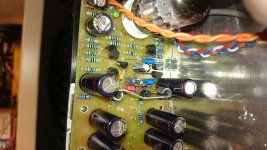
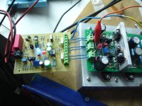
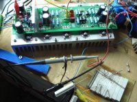
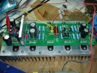
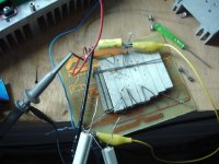
A good friend,Gerd (cool water)donate me with a couple of assembled boards.
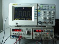
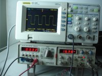
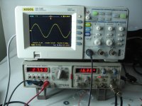
After a little retouch ,boards tested today.
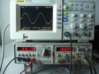
Power supply +/-50v
54.000uf/rail
Unloaded ripple=5mV
Loaded ripple=20mv
Idle current=20mA
Offset=30mV(input shorted)
Rload=6R
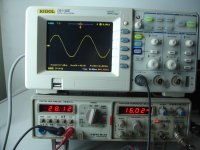
Inp.1.2vRMS
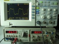
Out=28vRMS unclipped/6R=130wRMS OR 196w RMS/4R
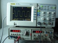
-3db down to 3hZ(Tested at 5vRMS & at full power )
-3db up to 300khZ. Tested at 5vRMS/6R
Noice=200μV(Input shorted)
Input IPS=Wolverine
After a little retouch ,boards tested today.
Power supply +/-50v
54.000uf/rail
Unloaded ripple=5mV
Loaded ripple=20mv
Idle current=20mA
Offset=30mV(input shorted)
Rload=6R
Inp.1.2vRMS
Out=28vRMS unclipped/6R=130wRMS OR 196w RMS/4R
-3db down to 3hZ(Tested at 5vRMS & at full power )
-3db up to 300khZ. Tested at 5vRMS/6R
Noice=200μV(Input shorted)
Input IPS=Wolverine
Attachments
-
 DSC09582.JPG587.7 KB · Views: 155
 -
 DSC09581.JPG590.8 KB · Views: 138
 -
 DSC09580.JPG562.4 KB · Views: 135
 -
 DSC09579.JPG583.7 KB · Views: 137
 -
 DSC09578.JPG586.1 KB · Views: 164
 -
 DSC09577.JPG606.8 KB · Views: 200
 -
 DSC09576.JPG601.2 KB · Views: 400
 -
 DSC09575.JPG547.7 KB · Views: 410
 -
 DSC09574.JPG588.9 KB · Views: 429
 -
 DSC09572.JPG613.7 KB · Views: 443
Last edited:
30mV output offset. Is the amplifier DC coupled?................
Offset=30mV(input shorted)
...........
Noice=200μV(Input shorted)
..............
AC coupled should allow much less than 30mVoff
Noise @ 200µVac is about 10dB to 20dB noisier than most amplifiers can achieve.
I expect <0.05mVac (50µVac) from all my amplifiers and try to find out why they can't and eliminate the error.
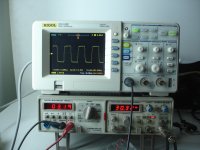
The last pic shows "CH1= 20.0V B"
What is that telling you/us about the clipping level shown on screen?
Last edited:
- Home
- Amplifiers
- Solid State
- Slewmaster - CFA vs. VFA "Rumble"