Hello All,
I just want to begin by saying that I am new here, and I was hoping to get some help on an amplifier design that I have been working on. I designed everything in Pspice and saw no signs of problems. I then built it on a breadboard and had some issues with oscillating, but by lowering the gain a bit and adding in some capacitors, I was able to get it stable. But when I was finally happy with a design and assembled it on a board, it started oscillating again! I consider this to be my first "real" design, so I was crushed when it didn't work. I have checked over my soldering work, and I am fairly certain that I assembled everything correctly.
I'm really frustrated by this failure, so I was hoping some folks on here would have some insight into why it might be oscillating and/or other suggestions for improving my design before I make another attempt. I imagine that this schematic will seem quite basic to the more experienced designers on here, but, for me, this design has been the product of months of self-study and experimentation.
The two power MOSFETs are IRF540N and IRF4905. I do not know if that is a common pairing or not, but I believe from the datasheet specs that they should be a fairly good match, and in practice the bias point of the output comes pretty close to 12V with about 150mA bias current for the resistor values shown.
Attachments

C23 looks a bit (a lot high) high.
C24 could be a big problem. Normally there would be a resistor of around 10 ohms in series with the cap. Check that out.
Adding a small resistor in series with the input cap (the 1uF) might help. Try something like 220 ohms to 1k.
Actual layout and implementation is hugely critical in any design like this.
Mooly,
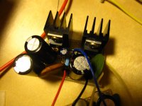
Thank you for the quick response. Both C23 and C24 were added in the breadboard phase to prevent oscillating. double checking my calculations, it seems I may have misplaced a decimal when calculating C23. I will correct that. I will look into C24. It is a large ceramic disc cap which should have fairly now ESR. I will look into taking some photos of physical layout. Suffice to say that the layout is extremely dense. the circuitry for Q3-Q9 are on one very small piece of perf board while the power transistors and their biasing resistors are on a second board. I have tried running the two boards from separate power supplies, but this has not helped.
Thank you for the quick response. Both C23 and C24 were added in the breadboard phase to prevent oscillating. double checking my calculations, it seems I may have misplaced a decimal when calculating C23. I will correct that. I will look into C24. It is a large ceramic disc cap which should have fairly now ESR. I will look into taking some photos of physical layout. Suffice to say that the layout is extremely dense. the circuitry for Q3-Q9 are on one very small piece of perf board while the power transistors and their biasing resistors are on a second board. I have tried running the two boards from separate power supplies, but this has not helped.
C24 is a big problem because you are loading the output of the amp 100% capacitively which is something many amps won't tolerate.
You still need the cap but it should have a resistive element to it as well. Just add a 10 ohm in series with it.
Why do I get the feeling that might be scary 😱
Try adding the 10 ohm first. Also you might find a small cap across R46, the 10k feedback resistor beneficial. Something in the region of 10pf (Pico).
You still need the cap but it should have a resistive element to it as well. Just add a 10 ohm in series with it.
I will look into taking some photos of physical layout.
Why do I get the feeling that might be scary 😱
Try adding the 10 ohm first. Also you might find a small cap across R46, the 10k feedback resistor beneficial. Something in the region of 10pf (Pico).
here are the photos of my layout. If the boards look wet, that is because I had just finished cleaning the flux off of them with rubbing alcohol.
Attachments
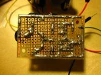

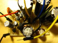
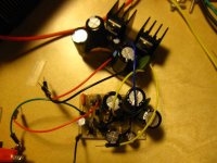
They are very neat and compact boards.
Try what I have suggested first, particularly adding a 10 ohm (anything about that sort of value) in series with the cap and a very small cap across the feedback resistor.
A lot of problems can show up when circuitry is strung out on boards that are interconnected with lots of wiring... so we'll have to see.
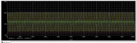
Also I'm a bit puzzled by the 'scope' shot which shows two signals that both seem to be 1kHz. Oscillation is usually at many 10's of kHz and above.
Try what I have suggested first, particularly adding a 10 ohm (anything about that sort of value) in series with the cap and a very small cap across the feedback resistor.
A lot of problems can show up when circuitry is strung out on boards that are interconnected with lots of wiring... so we'll have to see.
Also I'm a bit puzzled by the 'scope' shot which shows two signals that both seem to be 1kHz. Oscillation is usually at many 10's of kHz and above.
Mooly,
I have just finished resoldering the boards with a 10 ohm resistor in series with C24 and C23 changed to 6.8nF (by my calculations 1/(2*PI*1000*6.8*10^-9)=23.4 KHz cutoff? maybe I'm doing that wrong, though). I am going to retest now.
The "scope shot" is not from my O-scope, but rather the output from the Pspice simulation showing it operating normally. If you would like, I can hook it up to my scope and take a picture to show you what the real board does.
Last edited:
Just finished re-testing. No change.
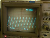
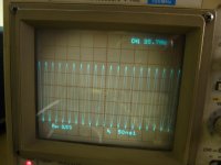
I have attached shots from the output. With both boards running from a single supply, the system oscillates at roughly 465KHz and also "motorboats" at low frequency. When running from separate supplies, the system oscillates at roughly 35 MHz and trips the current limiter on my bench supply (a 90W linear supply with the current limit set to roughly 1 Amp, which it should not be able to exceed in normal operation). On my breadboard, the layout was spread out quite a bit more, but was able to run stable from a single supply, which is why I am so confused that it oscillates after assembly. Perhaps I damaged a component somewhere during assembly?
I have attached shots from the output. With both boards running from a single supply, the system oscillates at roughly 465KHz and also "motorboats" at low frequency. When running from separate supplies, the system oscillates at roughly 35 MHz and trips the current limiter on my bench supply (a 90W linear supply with the current limit set to roughly 1 Amp, which it should not be able to exceed in normal operation). On my breadboard, the layout was spread out quite a bit more, but was able to run stable from a single supply, which is why I am so confused that it oscillates after assembly. Perhaps I damaged a component somewhere during assembly?
Attachments
Without discussing the value of C23, its opportunity or the suitability of its present location, I would suggest returning its cold end (now V+) to the ground: it will eliminate instabilities caused by imperfect bypassing/layout, without changing anything to the original design intent
Elvee,
I tried your suggestion. I had to change the position slightly to make it work. It only made a slight difference. Oddly, the design no longer peaks the current on my power supply, but still oscillates in the 400-500 KHz range.
I tried your suggestion. I had to change the position slightly to make it work. It only made a slight difference. Oddly, the design no longer peaks the current on my power supply, but still oscillates in the 400-500 KHz range.
All,
could the problem be from the fact that I am running the two separate boards from different supply leads? would it possibly help if I wired the power rails of each together with some relatively short/low resistance wire? possibly the additional sharing of smoothing caps might make a difference?
could the problem be from the fact that I am running the two separate boards from different supply leads? would it possibly help if I wired the power rails of each together with some relatively short/low resistance wire? possibly the additional sharing of smoothing caps might make a difference?
The layout and all the wiring could well be playing a big part. In the first post you mentioned the bias coming out roughly correct. Was that in simulation, or was it the real amp ?
Without simulating your circuit, my gut feeling is to get rid of C23 and C20. Add a 10ohm resistor in series with C24. Put a capacitor from base to collector of Q9 - try starting with 1nF.
I agree with this, it needs a miller cap, but i think something like 100pf or even lesser might do the job.Without simulating your circuit, my gut feeling is to get rid of C23 and C20. Add a 10ohm resistor in series with C24. Put a capacitor from base to collector of Q9 - try starting with 1nF.
I've just done a quick sim in LTspice of the circuit as it stands in post #1 and find it oscillates......
I'll have a look later and see what can be done.

I'll have a look later and see what can be done.
OK, I also did some analysis 😉
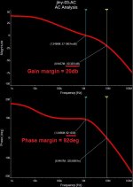
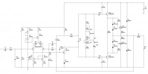
1-st picture - initial schematic AC analysis. Stability margins are obviously not enough, this is practically an oscillator by design.
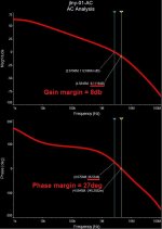
2-nd and the 3-rd pictures - leaving the output stage aside for a moment, just adding some emitter degeneration and a lead compensation capacitor - making the whole thing unconditionally stable.
Now - the output stage. DANGEROUS! And prone to local oscillations.
Gate stoppers - Mooly has gust mentioned. But there is a bigger problem. HexFETs are not self-regulating devices (Laterals are), so you need to setup a spreader, thermally-coupled with the output devices in order to keep their quiescent current stable and prevent the thermal runaway. You also need to drive the HexFETs from the low output impedance follower in order to tame their high non-linear output capacitance. IRF9540 is a better match for IRF540 - exactly because their capacitance characteristics are much closer.
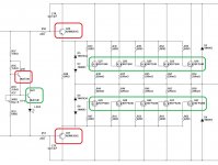
4-th picture - example of the working high-power output stage with even more interesting 2-point spreader. One of its transistors is thermally coupled with the drivers, placed on a separate local heatsink. The other one is placed on the main heatsink, together with the output devices.
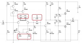
5-th and 6-th pictures - an example of your modified IPS+VAS section together with the adapted OPS. You can use IRF540/9540 there with no problem. You can see the good gain and phase margins. This one will work if you build it properly.
Note the Miller cap (C11) and the VAS load bootstrap (C4). The LED is Red one.
Let me know if you will have questions 😉
Cheers,
Valery
1-st picture - initial schematic AC analysis. Stability margins are obviously not enough, this is practically an oscillator by design.
2-nd and the 3-rd pictures - leaving the output stage aside for a moment, just adding some emitter degeneration and a lead compensation capacitor - making the whole thing unconditionally stable.
Now - the output stage. DANGEROUS! And prone to local oscillations.
Gate stoppers - Mooly has gust mentioned. But there is a bigger problem. HexFETs are not self-regulating devices (Laterals are), so you need to setup a spreader, thermally-coupled with the output devices in order to keep their quiescent current stable and prevent the thermal runaway. You also need to drive the HexFETs from the low output impedance follower in order to tame their high non-linear output capacitance. IRF9540 is a better match for IRF540 - exactly because their capacitance characteristics are much closer.
4-th picture - example of the working high-power output stage with even more interesting 2-point spreader. One of its transistors is thermally coupled with the drivers, placed on a separate local heatsink. The other one is placed on the main heatsink, together with the output devices.
5-th and 6-th pictures - an example of your modified IPS+VAS section together with the adapted OPS. You can use IRF540/9540 there with no problem. You can see the good gain and phase margins. This one will work if you build it properly.
Note the Miller cap (C11) and the VAS load bootstrap (C4). The LED is Red one.
Let me know if you will have questions 😉
Cheers,
Valery
Attachments

That's great work by vzaichenko  its saved me a job 😉
Actually, I tried to see if the original design could be tweaked, but whichever way you look at it, you are going to have to do a bit of a redesign.
This was my attempt at minimal alterations and additions. Its not perfect by any means and I think the compromises are to great. There is a problem with slew rate limiting at higher outputs and at high frequency that shows up on squarewave testing.
But hey... as your first attempt at amplifier design this is great 🙂


its saved me a job 😉Actually, I tried to see if the original design could be tweaked, but whichever way you look at it, you are going to have to do a bit of a redesign.
This was my attempt at minimal alterations and additions. Its not perfect by any means and I think the compromises are to great. There is a problem with slew rate limiting at higher outputs and at high frequency that shows up on squarewave testing.
But hey... as your first attempt at amplifier design this is great 🙂
That's great work by vzaichenko
Actually, I tried to see if the original design could be tweaked, but whichever way you look at it, you are going to have to do a bit of a redesign.
This was my attempt at minimal alterations and additions. Its not perfect by any means and I think the compromises are to great. There is a problem with slew rate limiting at higher outputs and at high frequency that shows up on squarewave testing.
But hey... as your first attempt at amplifier design this is great 🙂
View attachment 529861
View attachment 529862
View attachment 529863
View attachment 529864
Pretty much similar approaches

But IPS degeneration makes it so much less "nervous", that I strongly recommend using it, at least for the early prototypes - it can be reduced or even eliminated later on, assuming the design is stable in general and ready for a little bit of pushing to the limits 😛
Don't know if this has been mentioned but the original has a gain of 10. That's a bit low for a power amp, and will promote instability. Did you try raising it to 20 or 30?
Jan
Jan
- Status
- Not open for further replies.
- Home
- Amplifiers
- Solid State
- AB amplifier is oscillating. seeking critique