I'm at my last resort...
First time using a breadboard, first time making an active filter. I've done countless hours of research, and I can't seem to get this second order high pass to work. Reconfigured the board I don't know how many times, added a 5x gain path, and still nothing.
I have the incoming signal from my iPhone or iPad, output is going to a little 15w amp board. The output always sounds extremely quiet (much quieter than if I were to just touch the input and output ground and + to one another, bypassing the breadboard. Also, there is no audible change when I turn the power supply (12v) on vs when it's off. I'm currently using the +, -, and ground from the power supply, but I HD previously configured a rail splitter w/ two resistors and a cap, and hooked it up to the same power supply (power supply had its - and ground leads bridged from the factory. It's an eBay 0-30v variable power supply.
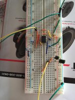
I rewired the board w jumper wires placed as clearly as possible, so I could post a photo for any of the experts here to lend a little wisdom.
Any help is greatly appreciated.
Components are:
Lm4562 opamp
.1 uF bypass caps
.0047 uF C1 & C2
75k R1 (the three resistors in series)
16k R2
First time using a breadboard, first time making an active filter. I've done countless hours of research, and I can't seem to get this second order high pass to work. Reconfigured the board I don't know how many times, added a 5x gain path, and still nothing.
I have the incoming signal from my iPhone or iPad, output is going to a little 15w amp board. The output always sounds extremely quiet (much quieter than if I were to just touch the input and output ground and + to one another, bypassing the breadboard. Also, there is no audible change when I turn the power supply (12v) on vs when it's off. I'm currently using the +, -, and ground from the power supply, but I HD previously configured a rail splitter w/ two resistors and a cap, and hooked it up to the same power supply (power supply had its - and ground leads bridged from the factory. It's an eBay 0-30v variable power supply.
I rewired the board w jumper wires placed as clearly as possible, so I could post a photo for any of the experts here to lend a little wisdom.
Any help is greatly appreciated.
Components are:
Lm4562 opamp
.1 uF bypass caps
.0047 uF C1 & C2
75k R1 (the three resistors in series)
16k R2
Attachments
Last edited by a moderator:
From the looks of your connections there is no power to the opamp (though I can't see the entire breadboard). There is nothing visibly plugged into the + on the right of the board (note that with my breadboard the top half and bottom half are separate circuits as well) and similarly I don't see anything on the negative row on the left side of the board.
Ideally you should use a split supply (assuming you have a dual rail opamp) otherwise you will need an output cap.
I would not advise connecting it to anything until you have checked voltages with a multi-meter, especially that you don't have any DC on the output.
edit: posting the schematic you are working from would help too 🙂
Tony.
Last edited:
Lesson #1: when your first breadboard came from eBay with zero description on the packaging, be sure to pull off the back adhesive strip to check whether the + & - buses go all the way down the length of the board.
Sure enough, mine are also separate circuits.

I'll hook up my power supply to the board again tomorrow, and check output with a multimeter. I've been using the right (-) bus hooked up to the ground port on my power supply, the right (+) hooked up the the + on my ps, and the left (-) hooked up to the - on my ps.
Tony, thank you very much for your help!
Sure enough, mine are also separate circuits.
I'll hook up my power supply to the board again tomorrow, and check output with a multimeter. I've been using the right (-) bus hooked up to the ground port on my power supply, the right (+) hooked up the the + on my ps, and the left (-) hooked up to the - on my ps.
Tony, thank you very much for your help!
hehe you might be able to tell, I've had a similar problem 😉 The multimeter is your friend!! don't assume always check 🙂
Tony.
Tony.
I'm at my last resort...
Also, there is no audible change when I turn the power supply (12v) on vs when it's off.
That is the telling sign. As Wintermute observes, your circuit is probably not powered - whether by mis-wiring or because the opamp is damaged. First, verify that the op-amp is being correctly powered by measuring the supply voltages directly at the device pins.
The broken red and blue lines indicate a break in continuity.
Troubleshooting can approached by simplifying the circuit.
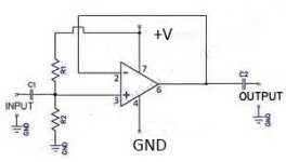
One way would be to remove all the present connections and connect the op amp as a voltage follower (-input to output jumper), with +input connected to the voltage divider. Once you have the op amp working as a unity gain voltage follower you can precede to installing the high pass filter components.
It sounds like you have a single output power supply, you will need to bias the +input with a two 24K voltage divider to provide a voltage half way between the power supply +/- terminals. The – terminal is GND. The op amp will require two capacitors one on the output and one on the input voltage divider to block the DC voltage.
Test the voltage follower: The voltage at the +input should be the same as the output voltage. Then you can connect the input and output to an audio source and amplifier. The op amp will not drive a speaker.
You will need an audio oscillator and scope to test the filter performance and frequency response.
Troubleshooting can approached by simplifying the circuit.
One way would be to remove all the present connections and connect the op amp as a voltage follower (-input to output jumper), with +input connected to the voltage divider. Once you have the op amp working as a unity gain voltage follower you can precede to installing the high pass filter components.
It sounds like you have a single output power supply, you will need to bias the +input with a two 24K voltage divider to provide a voltage half way between the power supply +/- terminals. The – terminal is GND. The op amp will require two capacitors one on the output and one on the input voltage divider to block the DC voltage.
Test the voltage follower: The voltage at the +input should be the same as the output voltage. Then you can connect the input and output to an audio source and amplifier. The op amp will not drive a speaker.
You will need an audio oscillator and scope to test the filter performance and frequency response.
Attachments
Last edited:
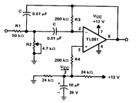
Here is an example of a single power supply High Pass Filter.
Voice Bandwidth Filter | Best For Circuit and Wiring
Voice Bandwidth Filter | Best For Circuit and Wiring
Attachments
Ok folks, went back to my rail splitter (two 1/2w resistors and a cap), got my power situated on the breadboard, checked it on the multimeter, plugged in the amp, and it worked like a charm!
Riding high, I even went and rigged up my low pass filter on the other side of the lm4562, and it all came together quite nicely.
Thank you all for your help... I was almost ready to give up
The output from the amp still seems slightly lower than bypassing the active filter circuit, but this could just be a perception bc my high pass is at 1000Hz.
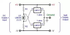
I think my next move on this project should be making my virtual ground from an LM317/337 pair. A bit more research is needed though, especially since I want to feed my amps from a 24v battery pack, and need to step down at the active filters... or use a 12v battery supply, power the active filter straight from that, and step up to 24v for the amps. Although, I recall reading that buck converters on amps produce noise.
Riding high, I even went and rigged up my low pass filter on the other side of the lm4562, and it all came together quite nicely.
Thank you all for your help... I was almost ready to give up
The output from the amp still seems slightly lower than bypassing the active filter circuit, but this could just be a perception bc my high pass is at 1000Hz.
I think my next move on this project should be making my virtual ground from an LM317/337 pair. A bit more research is needed though, especially since I want to feed my amps from a 24v battery pack, and need to step down at the active filters... or use a 12v battery supply, power the active filter straight from that, and step up to 24v for the amps. Although, I recall reading that buck converters on amps produce noise.
my next move on this project should be making my virtual ground from an LM317/337 pair.
This might help.
http://www.ti.com/lit/ds/symlink/tle2426-q1.pdf
Actually, I just realized that in creating that virtual ground, when I connect 24v of battery power, I will have +12v on one rail and -12v on the other... And the lme4562 is rated up to +/-17v, so I should be safe and not have any need for a DC-DC step down?
If you are planning on using batteries then using two twleve volt batteries wired in series, take a tap of the center point (ie the connection from +ve of one to the -ve of the other) and you have your + and - 12V from the floating Positive and -ve terminals of the two batteries.
However if you intend to use the 24V to power something else single supply then you will have a problem. (as you will have two different ground references, the centre tap for your opamp, and the -ve rail for your 24V...
I tried a split supply using resistors in the past but had poor performance, I suspect current wasn't adequate.
Tony.
Good to know, and thanks again, Tony.
I need to do some research on how people power their Bluetooth systems with one battery pack. You would need to have amplifiers, active filtering and preamp, and the Bluetooth module powered from the same source. In my earlier research last week, I found someone on here saying a Murata DC-DC converter would allow this without woes.
Would the tle2426 have enough current for this application? If not for just the active filtering, what about if I add a preamp to the circuit?
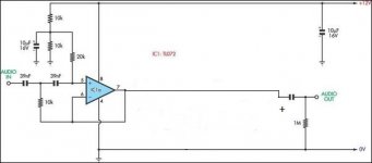
This is the virtual ground circuit I was thinking of building next:
I need to do some research on how people power their Bluetooth systems with one battery pack. You would need to have amplifiers, active filtering and preamp, and the Bluetooth module powered from the same source. In my earlier research last week, I found someone on here saying a Murata DC-DC converter would allow this without woes.
Would the tle2426 have enough current for this application? If not for just the active filtering, what about if I add a preamp to the circuit?
This is the virtual ground circuit I was thinking of building next:
Attachments
Rolls SX21 Tiny Two-Way Crossover uses the bias method.
The SX21 is a 24dB/Octave two-way frequency divider intended for small sound reinforcement applications. It has Input, Low and High Output jacks, and Input, Crossover Frequency, Low and High Output controls. It is powered by an included 12 to 16 volt DC adapter.
Rolls Corporation - Real Sound - Products SX21 Tiny Two-Way Crossover
http://www.rolls.com/pdf/IS_SX21.pdf
- Status
- Not open for further replies.
- Home
- Source & Line
- Analog Line Level
- What's wrong w/ my breadboard high pass??