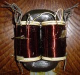
My current project is a Chinese pre-amplifier named after Mr. Curl's JC-2 and I decided to use an R-Core transformer.. From what I have read in other threads, the design is modeled after the JC-2 Actual but not the same so I call it the C-2. I received the transformer yesterday and was immediately confused by all the wires sticking out of the thing. My assumption was that primary leads would come out one end and secondaries would come out of the other. It's labeled as such but I'll check first. One reason I chose this particular R-Core is that it can provide two 18V-0.5A outputs and three 9V-.3A outputs. This can cover a lot of different applications.
Things I knew going in:
I would need a transformer
I heard that R-Core and Toroidal transformers create less "noise" than EI transformers.
Things I didn't know:
Any data pertaining to the C-2 like voltage requirements, line-in requirements etc.
R-Core transformers are built with the primary on one side and secondary on the other
One of the leads on the primary side is for a "shield", is this for shielded cable/wires or chassis ground?
There are two primary windings, can anyone explain the factors that would dictate when both are used? I assume I should use the primary that includes the "SCN" or "shield" lead.
Didn't know then or now, do I need some kind of power supply regulator?
Schematic and photos to follow
R-core and toroids leak less flux than EI trafos so there's less problem about locating them or screening them to achieved low hum levels in the final system. However they pass through more noise than EI (between primary and secondary) so there's a trade-off.
In cases where there are two primaries that's normally so the trafo works on both 115V and 230V mains. They should go in series if your mains is 230V and in parallel if you're on 115V.
Yes the shield goes to chassis which (for classI) also goes to mains earth.
In cases where there are two primaries that's normally so the trafo works on both 115V and 230V mains. They should go in series if your mains is 230V and in parallel if you're on 115V.
Yes the shield goes to chassis which (for classI) also goes to mains earth.
Not really. Since the primary and secondary are wound on opposite sides of the Racetrack (that's the "R" in "R-core"), the capacitive coupling between primary and secondary is tiny. Thus the injection of mains-borne RF hash, into the secondary, is also teeny tiny. On the other hand a conventional EI transformer with primary wound on the same bobbin as secondary, has orders of magnitude more capacitive coupling from primary to secondary. That's why EI transformer sellers are scrambling to convert to "split bobbin" winding arrangements. R-core is split bobbin, times ten.However they pass through more noise than EI (between primary and secondary) so there's a trade-off.
Edit- note to Thread Starter: John Curl himself (designer of JC2) has talked about Rcore transformers and split bobbin transformers, here on diyAudio. Do a few searches and read what he has to say. Maybe you'll find it helpful. Maybe you'll find it unintelligible gibberish.
Last edited:
I lumped toroids and R-cores together and yeah I was remiss in not restricting my remarks about EI's lower coupling to split bobbin types.
When I've made measurements of interwinding coupling (and done some quick back-of-the envelope estimations) the coupling via the core became significant. It looks like you're omitting that in your narrative about R-cores.
When I've made measurements of interwinding coupling (and done some quick back-of-the envelope estimations) the coupling via the core became significant. It looks like you're omitting that in your narrative about R-cores.
The Rcore transformers I have used all had primaries and secondaries wound on top of each other on each of the 2 bobbins. Split bobbin construction is possible with these types, but I've yet to see any. (I imagine they probably exist for some leakage critical application)
The Rcore transformers I have used all had primaries and secondaries wound on top of each other on each of the 2 bobbins.
That's the whole idea, an R-core transformer has balanced windings.
How else can cancellation work.
The better they are balanced, percentage/tolerance, the better the trick works.
Reason for me to blueprint low-cost serial manufacture R-core transformers.
kevinkr is right. Primary and secondary should not be wound on separate bobbins unless high leakage is desired (which is generally a bad thing). Even if somebody needs high leakage, R core is a bad choice for this type of winding, since that core has low core loss only in case flux is parallel to the core windings. Flux being perpendicular to the sheet loss is ~100 times higher.
Absolutely not recommended.
Always use both primaries!
R-Core transformers are built with the primary on one side and secondary on the other
Absolutely not recommended.
There are two primary windings, can anyone explain the factors that would dictate when both are used?
Always use both primaries!
I was reading the info from this website:
Products - Custom Magnetics, Inc.
It says that primaries and secondaries are wound on separate bobbins which I mistook for separate sides. If I only need one 18V secondary, will it still be balanced?
Products - Custom Magnetics, Inc.
It says that primaries and secondaries are wound on separate bobbins which I mistook for separate sides. If I only need one 18V secondary, will it still be balanced?
This manufacturer of Rcore transformers also appears to say that there are two bobbins (not four), one bobbin placed on each long leg of the Racetrack, with the primary windings on one bobbin/leg and the secondary windings placed on the other bobbin/leg:
Although, as others have stated here, it would be far more balanced to have four bobbins instead of two. Put one primary bobbin/winding and one secondary bobbin/winding on the left leg of the racetrack, and put the other primary bobbin and the other secondary bobbin on the right leg of the racetrack. For perfect balance you want to ensure the primary currents are identical (which is easy to do), AND you want to ensure the secondary currents are identical (which is less easy). John Curl's design solution is to use shunt voltage regulators fed by constant current sources. If you match the two constant current sources, then the current drawn from DC_V- equals the current drawn from DC_V+, and so the currents in the transformer secondary windings are identical.
BTW here are a couple of posts by John Curl, praising the Rcore for high end preamp use: {post #7389} . . . . . {post #919}
Home » Products » Linear Transformers » R-Core Transformers
R-core Transformers are manufactured using unique rectangular cores with round cross section known as R-cores. The special feature of this transformer is that the core has no gaps and is continuous.
The other unique feature of R-cores is the use of Bobbins in two parts. The winding is done on special round bobbins on two parallel legs of the core. This ensures complete isolation between the two windings and satisfies safety standards. In comparison with EI Transformers of same capacity, the R-core transformer is compact (nearly 40% smaller) and has a low temperature elevation. Leakage flux of the R-core transformer is about 1/10th of conventional transformers which permits the equipment manufacturer to place the transformer close to critical electronic components. The balanced winding & low leakage flux ensures low noise of the transformers. This makes R-Core transformers suitable for use in noise sensitive equipment.
The R-core Transformers have found wide application in CRT display units, audio equipment, satellite receivers, bio-medical equipment, printers, photo-copier machines, weighing scales, etc.
Although, as others have stated here, it would be far more balanced to have four bobbins instead of two. Put one primary bobbin/winding and one secondary bobbin/winding on the left leg of the racetrack, and put the other primary bobbin and the other secondary bobbin on the right leg of the racetrack. For perfect balance you want to ensure the primary currents are identical (which is easy to do), AND you want to ensure the secondary currents are identical (which is less easy). John Curl's design solution is to use shunt voltage regulators fed by constant current sources. If you match the two constant current sources, then the current drawn from DC_V- equals the current drawn from DC_V+, and so the currents in the transformer secondary windings are identical.
BTW here are a couple of posts by John Curl, praising the Rcore for high end preamp use: {post #7389} . . . . . {post #919}
If I only need one 18V secondary, will it still be balanced?
Connect the two secondaries in parallel.
First of all, thank you to all. Comprehensive explanations and simple elegant solutions help move things along.
Secondly, there sure are a few different configurations for R-Cores. I probably picked the perfect one to learn on.
With the suggestion to combine the two 18V legs in parallel that still leaves me three 9V .3A sources, can I combine two of those into one, then run that one 9V .6A leg in series with the last 9V .3A winding to get another 18V then run that one parallel with the combined 18V? Or will there be an issue with combining windings of differing amperage?
I'll read up some, thank you Mark for the references.
Rcores should have half the primary and half the secondary on each limb.Not really. Since the primary and secondary are wound on opposite sides of the Racetrack (that's the "R" in "R-core"), the capacitive coupling between primary and secondary is tiny. Thus the injection of mains-borne RF hash, into the secondary, is also teeny tiny. On the other hand a conventional EI transformer with primary wound on the same bobbin as secondary, has orders of magnitude more capacitive coupling from primary to secondary. That's why EI transformer sellers are scrambling to convert to "split bobbin" winding arrangements. R-core is split bobbin, times ten.
Edit- note to Thread Starter: John Curl himself (designer of JC2) has talked about Rcore transformers and split bobbin transformers, here on diyAudio. Do a few searches and read what he has to say. Maybe you'll find it helpful. Maybe you'll find it unintelligible gibberish.
Some to save money may put the whole primary on one limb and put the whole secondary on the other limb. That is NOT the way an Rcore should be manufactured. Doing this would make the construction "unbalanced". Yet one claim for the superiority of an Rcore over other types is that they are "balanced". This "balanced" requires that the primaries and the secondaries are split between the two limbs/bobbins.
Last edited:
That is the correct way to manufacture an Rcore.The Rcore transformers I have used all had primaries and secondaries wound on top of each other on each of the 2 bobbins. ................
I wrote a report as recently as 5th Dec 2015.
http://www.diyaudio.com/forums/parts/283421-selectronic-rcore-transformer.html?highlight=rcore
Last edited:
Shilchar place half the primary and half the secondary on one bobbin on one limb and place the other half primary and the other half secondary on the other bobbin on the other limb.This manufacturer of Rcore transformers also appears to say that there are two bobbins (not four),
I have three of their transformers and as mentioned in my previous post I have reported on the stupid phasing of their "colour codes" where they have mixed up the half winding colours and given no instructions on how to wire them correctly !!!!!!!!
No. Each limb/bobbin has both a primary winding and a secondary winding.one bobbin placed on each long leg of the Racetrack, with the primary windings on one bobbin/leg and the secondary windings placed on the other bobbin/leg:...................
Actually my transformers are dual secondary and dual primary.
So each bobbin has one primary and two secondaries. That makes two primaries and four secondaries on the two bobbins.
I'll repeat what I said earlier. Half the primary/ies and half the seconadry/ies are on each limb.
Last edited:
Low leakage flux in a trafo can be maintained only 1 way: primary must be inside the secondary or vica versa. Comparing leakage of trafos without mentioning specific primary to secondary arrangement is serious lack of knowledge or even lie.
1 primary and 1 secondary on each leg is not neccessarily better then primary on 1 leg and secondary on other. Maybe even worse.
1 primary and 1 secondary on each leg is not neccessarily better then primary on 1 leg and secondary on other. Maybe even worse.
I am not a big fan of R-core transformers. As far as I get it their claim to fame is a round cross section of the core allows for easier winding of the coils, so many of them do not use bobbins. Secondly since they are tape wound there are no gaps in the magnetic path, hence less flux leakage. The other advantage is that the square core means they take up less space than a toroid.
My measurements on one sample showed it did pass line noise better than any other transformers tested. Not a benefit. That sample had green used for a hot lead so it is really not an acceptable product.
Now I just bought on eBay two TOA A512 amplifiers which use R-cores for their power supply. Toa 500 Series Amplifier A 512A R914801 | eBay
A current project for one of the guys here is to build an amplifier. So it is actually cheaper to start by taking apart one of those amps and reusing many parts. The actual amplifier in them is a very old design using interstage transformers, last I looked.
Last edited:
Low leakage flux in a trafo can be maintained only 1 way: primary must be inside the secondary or vica versa. Comparing leakage of trafos without mentioning specific primary to secondary arrangement is serious lack of knowledge or even lie.
1 primary and 1 secondary on each leg is not neccessarily better then primary on 1 leg and secondary on other. Maybe even worse.
No, many transformer cores are assembled from pieces and have air gaps which increase flux leakage. In a standard E-I core there are even holes punched in the corner to help control flux density.
When you wind the secondary over the primary you can get better coupling. Not the same thing as leakage. You also get better coupling of the line noise.
One primary and one secondary per bobbin with two bobbins allows more uniform flux through the core and the option of dual primaries and secondaries.
Learn magnetics first! Every statement in this post is false or irrelevant. Too much work to correct them. You don't know what leakage is and how it is generated.
Learn magnetics first! Every statement in this post is false or irrelevant. Too much work to correct them. You don't know what leakage is and how it is generated.
We are talking about flux leakage. That induces voltage into nearby components and the chassis.
Attached are four pictures.
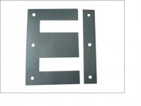
The first shows classic E-I core pieces. Note the holes. They are used for mounting but the size and location is to make sure the flux distribution is uniform.
The second shows a small transformer mounted to a chassis with leads connected to measure the voltage induced into chassis from the transformers flux leakage. Many transformers were measured this way.
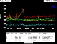
The third shows the actual FFT of the flux leakage measurements.
The final one shows the output noise from various types of transformers with fed from the AC mains with noise added.
Attachments


- Home
- Amplifiers
- Power Supplies
- R-Core Crash Course