I figured I'd ask here before I get to work on this simple pre-amp.
What compontent/s would I need to change or add to make this circuit work with LME47720NA? For OPA1632 I wouldn't need to change much if anything from my, very limited understanding.
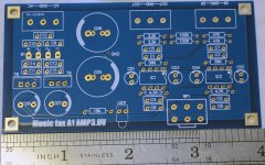
Resistor values are marked on the PCB.
C5,C6,C7 and C8 looks to be 220nF (0.22) from pics of populated boards.
C1,C2,C3 and C4 looks to be 10nF (0.01) from pics of populated boards.
The caps around the rectifying bridge and voltage regulators I assume are 100nF.
The two big lytics seem to be 2200uF, the smaller after the 7x12's I can't see, but should be easy enough to find out from the datasheets.
If anyone has the schematic, I'd be grateful if I could get it. I've contacted the seller twice about it now(most recently in the last 5 minutes).
What compontent/s would I need to change or add to make this circuit work with LME47720NA? For OPA1632 I wouldn't need to change much if anything from my, very limited understanding.
Resistor values are marked on the PCB.
C5,C6,C7 and C8 looks to be 220nF (0.22) from pics of populated boards.
C1,C2,C3 and C4 looks to be 10nF (0.01) from pics of populated boards.
The caps around the rectifying bridge and voltage regulators I assume are 100nF.
The two big lytics seem to be 2200uF, the smaller after the 7x12's I can't see, but should be easy enough to find out from the datasheets.
If anyone has the schematic, I'd be grateful if I could get it. I've contacted the seller twice about it now(most recently in the last 5 minutes).
Attachments

Do you mean LME49720NA ? If so then that would probably (but never 100% guaranteed) be OK. It would help to see the actual circuit though.
The OPA1632 is not suitable as its a totally different type of device, a full differential input and output.
The OPA1632 is not suitable as its a totally different type of device, a full differential input and output.
Do you mean LME49720NA ? If so then that would probably (but never 100% guaranteed) be OK. It would help to see the actual circuit though.
The OPA1632 is not suitable as its a totally different type of device, a full differential input and output.
Yes, that's what I meant. Typo, I make alot of those unfortunately.
I was recommended to use the OPA1632 to replace NE5532 in the BCL clone IIRC.
Anyway, I got two LME49720NA and LME49710NA(single so won't fit, I know) at a good price from a domestic online source.
So they are the real, that's good to know.
I've contacted the seller as I wrote, if I don't get any response I'll have to reverse engineer the board with a DMM...not looking forward to that tbh.
The OPA1632 is nothing like a 5532. For one thing its a single opamp and as you can see here, its a different type of device altogether with a differential output (two outputs, a + and a -)

The OPA1632 is nothing like a 5532. For one thing its a single opamp and as you can see here, its a different type of device altogether with a differential output (two outputs, a + and a -)
View attachment 526524
So it is, that goes to show I should do my own homework.
Thanks for pointing that out, could have ended up in blue smoke..
I presume whoever recommended that was thinking of OPA1642 or 1652 or similar, which are regular dual opamps. 1632 is the "odd one out", so to speak.
I presume whoever recommended that was thinking of OPA1642 or 1652 or similar, which are regular dual opamps. 1632 is the "odd one out", so to speak.
Yes, I probably got them mixed up.
No harm though as I think the OPA1632's might be used as a gain stage before a transformer output on a Vout DAC?
Would the 1642 be a plug in replacement for the NE5532?
I do have the LME47920NA's, but it's nice to have options.
I've got OPA1652 & OPA2132 on the way as well as I'd like to try a few different options.
In stock already:
OPA2134
OPA2604
OPA2107
OPA2111KP
NE5532
LM4562
LME47920NA
AD8066
LT1112
And a few others, those are the ones I remember without having to go look.
In stock already:
OPA2134
OPA2604
OPA2107
OPA2111KP
NE5532
LM4562
LME47920NA
AD8066
LT1112
And a few others, those are the ones I remember without having to go look.
I'll have to meaure the PCB with a DMM to get a schematic as the two messages to the seller has gone un-answered...
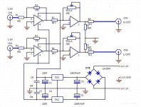
Its a Musical Fidelity X-A1 clone
very simple circuit
Thanks 🙂
There seem to be some more spots for caps on my PCB though.
I've not figured out the values for the small lytics close to the opamps yet.
The filmcaps fitted are Wima MKS2 220nF and the empty spots next to them will be 10nF MKT's. Those values determined from looking at ready made listings of this on ebay as well as kits.
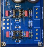
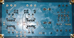
The backside is a mess I know, I will clean that all with IPA when all parts are populated.
Attachments
They are all on the PSU lines to the opamps.
The diagram only shows C5 and C6 where C1-C8 on the PCB.
i.e.
C8 & C4 are on the + supply to pin8 IC1
C2 & C6 are on the + supply to pin8 IC2
C1 & C5 are on the - supply to pin4 IC1
C3 & C7 are on the - supply to pin 4 IC2
They are all PSU caps meaning the actual circuit is correct albeit the PSU is simplified in the diagram. All irrelevant for the opamp rolling.
Last edited:
Thanks 🙂 yes I was leaning towards that as well while looking at the pics.They are all on the PSU lines to the opamps.
The diagram only shows C5 and C6 where C1-C8 on the PCB.
i.e.
C8 & C4 are on the + supply to pin8 IC1
C2 & C6 are on the + supply to pin8 IC2
C1 & C5 are on the - supply to pin4 IC1
C3 & C7 are on the - supply to pin 4 IC2
They are all PSU caps meaning the actual circuit is correct albeit the PSU is simplified in the diagram. All irrelevant for the opamp rolling.
Try LME49720HA in there if you can or maybe some discrete opamps???
I have one discrete opamp using 4pcs 2sk170's of which two are CCS's.
I think I'll try the 49720's as you suggest.
Atleast to start with, then I'll decide if I'll upgrade to something else.
- Status
- Not open for further replies.
- Home
- Source & Line
- Analog Line Level
- Components change to swap opamp?