Don't forget to fit them the other way round to the MPSAs!
C-B-E versus E-B-C
(sorry for my mistakes in posts 1961 and 1963. I think I have developed lexdysia)
C-B-E versus E-B-C
(sorry for my mistakes in posts 1961 and 1963. I think I have developed lexdysia)
I have thought about it but never tried.Andrew. Have you ever made a transistor Vceo tester? My brother said it was a device with a very high voltage with a very low current. The transistor would be increased in voltage until it failed. When taken from circuit it would be OK as the current was so low. The failiure maked by the transistor attempting to short the PSU.
One could select BC550C.
In am told BD139/140 are selected BD135/136. A machine tests as it goes for this. This possibly means some make 90 V.
A Variac powering a standard 230:100Vac to 200Vac secondary rectified to high voltage DC could easily be used.
A couple, or more, 1M resistors strung in series would turn that into a CCS.
The BJT should pass near zero uA when base is shorted to emitter.
If breakdown starts to occur as Variac is turned up, then the resistor voltage would appear to increase due increased Ie through the CE leads.
I'm afraid I chicken out and just use a higher Vce0 transistor if that is what the circuit needs.
Could you explain this a bit more?There will be no change in LTP stage gain for reasons given in post #1902.
Higher gain transistors, BC547C or BC550C will increase the Miller capacitance between the collector and base of the feedback return transistor.
That will work against the design improvements to increase the LTP current delivery rate and reduce the constraint on the nfb return path.
..........
I would love a thread on Vceo machine rather than a thread on why CD is better than LP even if you don't think so.
Cob on BC550 is rather good. I doubt a LTP is critical. The delay time across is a LTP issue. Some even think them a bad idea. I can see why. You can feed the signal into the minus input. That should solve most of that. If that resistor is 3K and the other lets say 82K it could be made to work.
Cob on BC550 is rather good. I doubt a LTP is critical. The delay time across is a LTP issue. Some even think them a bad idea. I can see why. You can feed the signal into the minus input. That should solve most of that. If that resistor is 3K and the other lets say 82K it could be made to work.
It takes about 10 secs to start a thread by pressing the "new thread" button at the top of the page in the appropriate forum and typing in a clear and specific thread title. Otherwise, replies might not be helpful. This seems like the perfect opportunity to try it in the Test Equipment forum, by either searching there, opening a 'request for contributions' thread or just reinventing a zener tester for yourself and posting an up-to-date design as a general purpose BV tester for comments.I would love a thread on Vceo machine....
Zener checker circuits can be based on anything with a fairly stable voltage output, from a 555 oscillator and miniature speaker transformer to a tiny ringing choke SMPS. They only need operate for as long as reading the voltmeter requires and there is no risk of damage if the current is limited to microamps. 9V or AA batteries have long been used to power such testers and they are relatively safe and useful for most semiconductor breakdown voltages. These days, USB power is the go and it sure is a relief to have new equipment so fitted and be free of so many batteries that are always dead when you need them.
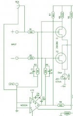
For those preferring mains power, you can use just the appropriate HV section shown in fig.4 of ESP's transistor tester design. Project 31 - Full Featured Transistor Tester
I built a kit for a comprehensive semi. tester around 25 years ago and it still serves me fine, with a single range of BV test up to approx. 140V. There are numerous traditional discrete and NE555 based HV generator designs up to typically 120V on the net and with a little updating could work fine too.
Last edited:
Could you explain this bit more?
With the LTP, the simplest formula to calculate the gain of a common emitter amplifier is to multiply the transistor trans conductance which is measured in milli-Siemens (mS) by the collector load in k.Ohms - represented by Av = gM *RL
The gM part is a measure of milliamps/volt - the value depends on the current and absolute temperature. The relationship between the latter is given by Ic/(q/KT) where K is Boltzman's constant and q represents electron charge.
q/KT equates close to 26 mV at room temperature, thus 1 m.a./ 0.026V gives a gM value of 38.46 mS per milli-amp of current. If the transistor junction temperature is lower than this and q/KT is taken as 25 mV then gM works out at 40 mS per milli-amp of current and this value can be used for rule of thumb calculations.
Leaving the variables of current and temperature aside, the latter being less variable, what remains is fixed by physics.
In the NAP140 the standing current in TR1 is 0.5 milli-amps and the collector load is 1k so gM is 20 and multiplying these the result is a gain of 20. In the NAP200 the current is some 2 milliamps giving gM of 40 multiplied by .27k giving a gain of 21.6
Interestingly, in relation to other than Naim amplifiers, the q/KT value of 26mV crops up as the ideal voltage drop across the emitter resistor of Class AB output stages.
I will answer about Miller capacitance in a separate post.
Last edited:
With the LTP, the simplest formula to calculate the gain of a common emitter amplifier is to multiply the transistor trans conductance which is measured in milli-Siemens (mS) by the collector load in k.Ohms - represented by Av = gM *RL
The gM part is a measure of milliamps/volt - the value depends on the current and absolute temperature. The relationship between the latter is given by Ic/(q/KT) where K is Boltzman's constant and q represents electron charge.
q/KT equates close to 26 mV at room temperature, thus 1 m.a./ 0.026V gives a gM value of 38.46 mS per milli-amp of current. If the transistor junction temperature is lower than this and q/KT is taken as 25 mV then gM works out at 40 mS per milli-amp of current and this value can be used for rule of thumb calculations.
Correction. Not that it makes a significant difference for rule of thumb assessments, the gM would be higher if the junction temperature is higher than 25 degrees C room temperature.
Re Miller Capacitance, this equals the collector to base capacitance of a transistor multiplied by (1 +Av). One can use the gM formula rule of thumb method and the datasheet value of the transistor in question.
This may tell you that an MPSA06 in a common emitter amplifier will develop more gross capacitance than a BC239C or BC550C.
Where hFE assumes importance is in the value of transistor R.in since the gross capacitance is developed across this.
If the transistor is passing 2 m.a. and has a gain of 50 the value will be 600 odd ohms. With a device having a gain of 250 the value will be over 3000.
A calculator may assist in seeing how this changes things eCircuitCenter
I can't agree.
If one fixes the VAS/TIS transistor and that runs at the same temperature then the Vbe applied to the collector load is fixed.
Let's assume that the VAS Vbe is fixed at 600mVbe
Now set the collector load to 600r, or 1200r, as two convenient values passing 1mA, or 0.5mA, down through one half of the LTP.
The gm of the LTP Q is 1m/0.026 =38.46ms (as you stated in post 1986)
The gain is gm * Rload = 38.46*600 = 23.08times.
For the higher collector load the gm is 0.5m/0.026 = 19.23ms
and the gain is 19.23*1200 = 23.08times.
The gain has not changed when the LTP temperature is unchanged.
The VAS/TIS Vbe controls the current and sets the gain of the LTP
Moving to capacitance.
The Vce of the LTP remains at the same voltage whether {Vsupply minus Vbevas} is set by a lower, or a higher, collector load.
If the Vce stays the same and the gain stays the same, then the multiplying effect on Cob should be the same.
I can't see how you arrive at the input LTP half changes Miller capacitance.
Now you stated
What is the Miller capacitance effect at the other side (the feedback node)?Higher gain transistors, BC547C or BC550C will increase the Miller capacitance between the collector and base of the feedback return transistor.
Last edited:
Something no one seems to have thought to ask is what sound quality difference will various LTP transistors give? I suspect and haven't a clue if correct is that noise is the only difference. As stated before very low noise might make the amplifer sound sweeter. BC550CG is very low noise as is BC337-40.
As I said before roughly. The best LTP is no LTP. The nearest you can do without nightmare problems is go in via the 1K minus input. If anyone needs to know I will draw that and how to do a better version. If you belong to some schools of thought not to do so is folly. I don't belong to that group, but have to submit to the technical excellence of the idea.
Even totally daft devices like MPSA42 should work as TR1/2. In fact many amps used MPSA92 for these duties. The stated reason being " highly linear ". This is a little hard to understand as an amplifier like this is made linear by use of loop feedback. That statement will fall apart if trying to get the last word in performance. The reason for that being due to Cdom we run out of negative feedback at the high frequency end of the audio band. Thus it is worth trying. An analogy being the pistons in your car will do 10 000 rpm. They never will, but no harm if they can. They will with ease if wondering. Like the amplifier the other things will not. Analogy only and the engine is different. We also add linearity if we use TR1/2 emitter resistors. Personally I feel Re+re = 50 is about right. If Naim it gets a bit more complicated. Best left alone.
2N5551 although OK might sound worse. Blue sounds.
2N4401 is a switching device that will work ( below 40V alas ). They have no specified audio use. Engineers found they worked very well and took the numbers off to keep it secret. A very simple ciruit using them or 2N4403 PNP and a 741 op amp might be heard in many LP's you own as a microphone preamp. A resistor taken from output to the -ve rail ( class A ) as a final Cinderella transformation. If using NE5534 this can be taken further by switching off it's intenal input pair ( LTP ) and taking the signal in through NE5534 compensation terminals via the new LTP. A state of the art microphone preamp for £1. It should be good enough for £500 microphones. Even the LM741 would be better than you might think. The really neat trick is the feedback automatically ajusts the servo function of the op amp to accept the new devices ( TL071/LF351N seems not to due to JFET inputs). It is this servo function we treasure in the LTP. It does more good that harm. It also makes simple power supplies OK to use. It ignores the hum it receives via that route as it is a common mode signal ( CMRR ). Even with a simple tail resistor it can have 90 dB rejection and no TR3! We have and need a differential signal to work our LTP. We can inject feedback also to form desirable correction into the anchored side at TR2. Usually signal into TR1. It can be TR2 if we choose. The reason we don't mostly is we make driving the input harder. Other than that TR2 is slightly better. Where this isn't true is delay time in the LTP, it is what it is. Some think using TR2 input cures that. Cure no. Better, yes. One transistor is far far better ( compound pair is best as that ). I wouldn't ever try it if you are given to prefering an easier life.
The " highly linear " is possibly true. Many transistors of 300V rating were for TV. Many were used as RGB drivers on the TV tube ( grid drivers ). Very simple SE class A circuits that had no negative feeedback. If the linearity of these was poor the shadows in black and white films would show a colour cast. In theory the linearity if the same of the 3 guns it would be OK. Not exactly as the colours did not have exacly the same drive requirements. It's surpriising it worked so well to stretch the near pentode curve ( like VAS ). It could even change with level from blue to green when bad at various levels ( dying tube that had been reset to extend life ). BF469/470 come to mind. These might be BF720/721 in the SMD we now have. Were it not for people who possibly came up via valves these devices might have been overlooked as they do not seem at first glance to be suitable. Were it not for tube TV I doubt these devices would exist now. They do because they have many new uses.
All of the Naim and similar amps exploit the better opperation of a transistor as a current amplifer. Only the VAS or I to V converter could be a major factor if discussing linearity. Two ways. The current flow into the VAS is highly debatable as to how well it works. N200 looks to that by making more current available. The linearity of the VAS up to it's CCS ( TR6 ) is a typical curve. It is rich in second harmonic which is nice to the ear.
The output stage is what it is. It's not bad. Again a pure current amplifier with voltage gain just over 90% or close.
I can't agree.
If one fixes the VAS/TIS transistor and that runs at the same temperature then the Vbe applied to the collector load is fixed.
Let's assume that the VAS Vbe is fixed at 600mVbe
Now set the collector load to 600r, or 1200r, as two convenient values passing 1mA, or 0.5mA, down through one half of the LTP.
The gm of the LTP Q is 1m/0.026 =38.46ms (as you stated in post 1986)
The gain is gm * Rload = 38.46*600 = 23.08times.
For the higher collector load the gm is 0.5m/0.026 = 19.23ms
and the gain is 19.23*1200 = 23.08times.
The gain has not changed when the LTP temperature is unchanged.
The VAS/TIS Vbe controls the current and sets the gain of the LTP
I avoided going into the Vas load on the input TR since explanations of that could cause some confusion to some observers whereas the LTP does not deliver a great deal of forward gain anyhow.
The basis of your argument is about a static condition assuming the Vas TR vbe is fixed at 600 mV.
I looked at this from a dynamic viewpoint since the current supplied by the input TR to the Vas TR base emitter junction (a diode) would vary under signal conditions and the current variation would involve the same in Vas TR Vbe and RIn loading effects on TR1 collector.
Moving to capacitance.
The Vce of the LTP remains at the same voltage whether {Vsupply minus Vbevas} is set by a lower, or a higher, collector load.
If the Vce stays the same and the gain stays the same, then the multiplying effect on Cob should be the same.
I can't see how you arrive at the input LTP half changes Miller capacitance.
Now you stated What is the Miller capacitance effect at the other side (the feedback node)?
A reduction of collector load from 22k in the NAP140 to 5k6 for NAP200 will be beneficial in tuning Miller capacitance to suit higher speed output transistors.
When the feedback transistor collector load is high the voltage seen at the collector is reduced. The amount of capacitance developed between collector and base is inversely proportionate to the square root of voltage.
Within the transistor there are two depletion layers one between the collector and base (that between base and emitter is not material here)
The greater the collector voltage the greater will be the width of the collector (by expansion into the collector base depletion zone) and the less will be the width of the base.
Reducing the collector voltage works in the opposite way.
I have provided a link to a Miller Capacitance Calculator for people to do their own calculations. No-one seems to have used that and I have had no feedback. Instead of using the software I made a spreadsheet some time to examine some observations made by Dave S.
At the time I did not allow for the 1k resistor in the decoupling to earth arm of the nfb network as providing a discharge path for Miller capacitance currents. That would move the -3dB point a lot higher outside the audio range.
Unpolarised capacitors in the nfb decoupling arm have been seen as problematic in the past. What the effect of the discharging Miller capacitance has, if any, is another question.
Thanks for finding that. My similar idea is on my other computer that's having upgrades. This one runs XP and only 80GB. Some programs I run and prefer will not run on Windows 8 or 10. 7 just about works. I did try emulators, no good.
If wanting very low noise and good sound MC33079 can be run with inputs and outputs in paralell. I did this with a MC preamp for Lyra Helikon. 3 op amps as a gain stage of 62 with passive 75 uS then the final op amp as active 3180/318 uS at gain 17 @ 1kHz. If building a pre amp this is a nice cheap op amp that sounds very good. Don't clone Naim preamps.
The NC200 addresses the need to drive Cdom ( TR4 collector to base amplifier stability capacitor ). The problem with amps of the single VAS type is it's like a one legged bicyclist. It is by his boot fixing alone he pulls the peddle upwards. Having a more powerful leg is all we can do as a fix. Douglas Self has said more or less never look at the twin VAS ( two legs ). I won't say more as I think it's obvious what I think. The minor objection is one needs to test each amp. When did that ever hurt something?
Cdom is the Elephant in the room with this amp. If the LTP is driven by a low resistance feedback loop it might marginally help with LTP capacitcance ( Cbe ? not Ccb ? ). 2K7 100R 470 uF 35 V non polar. All of these would piggy back the existing ones without removing parts. Be sure parts well soldered as very low gain could be problem ( smoke usually ). Very high gain will be less of a problem although might give you a shock as to volume. Remember the output stage is able to supply >3 amps of current so can drive what we like as a sensible feedback loop. DC offset would suffer. If the input resistor to TR1 was made 3K it might just work. This isn't a serious suggestion. It's just to state the options. As a more likely option 4K7 input and upper feedback arm and 180R lower feedback arm. 330 uF feedback cap. Most preamps will drive 4K7. If the DC offset is below 80mV I would leave the input as standard and try my original idea. It might just sound like you had spent much more money and costs almost nothing. I would exspect less fizz. There is even a suggestion moderate levels of DC offset sound better. It might help the process of a real speaker load and feedback.
Raising the gain a little somethimes helps sound. Long before the feedback is too little the stability change is changing the sound ( Cdom again ). You should find it sweeter, but perhaps less hard hitting. The 1K lower feedback arm could be made 500R by adding another 1K. Don't rush to change the capacitor. This will be something learnt you would never guess and there is no downside I can think of. Slightly more hiss and hum perhaps. Don't what ever you do go the other way.
A bit of a strange one this morning with the NAP 200 clone.
I've been leaving it powered-on permanently over the past few days now I've gained a little more confidence in it. This morning, however, there was a faint 50Hz hum audible from both speakers. Not loud, but loud enough to be heard when the room was quiet. The amp was working fine otherwise and the chassis was cold to touch.
I disconnected the pre-amp but this made no perceivable difference to the noise.
I cycled the mains input (quick on and off - no fuses blew this time) and upon power-up the 50Hz hum had gone and the amp continued to work as normal. It's been on for about an hour now and the noise hasn't returned.
What could have caused this behaviour?
Try rotating the transformer. Sometimes it's a fix. Can also get into wires that way and other boxes. Where the wires exit the transformer the hum field can be higher.
Ah hum has driven me to within an inch of my life even with the input grounded still have it. The transformers are in a separated compartment along with cap banks (note1 I have 6 in each speaker and a 4 x over) ended up with same length ground cables with star ground (note 2 I do work with VFD up 1000kw it’s just a big class d amp with big voltages and cable lengths are important) lifted the ground on each amp with 100 ohm helped and used 2 core screened cable 1 core input to amp 2 core ground input and the screen back to star ground helped a lot. When I switch on first thing they do hum but go after 20 min, one thing that did cross my mind each one of the diodes in the bridge has a 0.01uf across it
BC239C looks risky to me. It's rated at 25V VCEO and it's used with 40V across the C-E. Maybe Naim were selecting them, but I would not risk this unless I had measured them.
I have received confirmation that BC239C is the part used for TR1/2 in the genuine NAP200. They are apparently matched by Naim, but I'm not sure on what parameters they are matched nor within what tolerance.
Interesting!
You would have thought they would have gone for BC237C.
My guess at the Naim selection process is:
1) Measure avalanche voltage, select >45V
2) Measure noise figure, select <2dB
3) Measure beta, pair them up.
Not sure if #2 is that important. Nigel believes it is. Why would Naim use a part that was such a faff, if not for low noise???
Interesting!
You would have thought they would have gone for BC237C.
My guess at the Naim selection process is:
1) Measure avalanche voltage, select >45V
2) Measure noise figure, select <2dB
3) Measure beta, pair them up.
Not sure if #2 is that important. Nigel believes it is. Why would Naim use a part that was such a faff, if not for low noise???
It was Naim themselves who confirmed so I have no reason to doubt the advice given. Through a couple of enquiries relating to the NAP 200, specifically the pairs of transistors covered by the plastic shields, I got to the point where they confirmed that BC239C was the original part, and then they, unprompted, gave me a price for a single transistor - just this side of 60 GBP (!). I'm not sure whether that includes installation, and presumably, matching with the other half of the pair.
Out of interest I took the pairs of BC239Cs out of my Nait 3 (NAC 90/3 power amp) and measured the beta values, which came out at 437 (TR1) and 455 (TR2) for one channel, then 711 (TR1) and 688 (TR2) for the other. The circuit closely follows the basic Naim design albeit with higher values of the LTP collecter resistors than those seen in the NAP 200. Based on these measurements it looks like for the Nait 3 they are being matched closely on beta at least, and not to 10% of each other as has been suggested elsewhere for this topology. Unfortunately my tester is very basic and doesn't measure any other parameters.
Last edited:
- Home
- Amplifiers
- Solid State
- NAP-140 Clone Amp Kit on eBay