Senani et al.
If one wants a pretty comprehensive account of CFAs and their variants, I can recommend Senani, Bhaskar, Singh and Singh, Current Feedback Operational Amplifiers and Their Applications. Springer, 2013, print book 978-1-4614-5187-7, available as an e-book. In a quick traverse I haven't found any errors as yet, and the English is quite decent. Lots of good references, and discussions of real parts.
If one wants a pretty comprehensive account of CFAs and their variants, I can recommend Senani, Bhaskar, Singh and Singh, Current Feedback Operational Amplifiers and Their Applications. Springer, 2013, print book 978-1-4614-5187-7, available as an e-book. In a quick traverse I haven't found any errors as yet, and the English is quite decent. Lots of good references, and discussions of real parts.
In apps the 7171 (and other P/N) with the buffered input is the best of both worlds. because of its linearity at HF, I think it can help with some situations... like HF getting into the audio circuits... via PS or I/O. It's linearity above audio has practical affects in the field (audio record/playback systems). It is an additional reason why CFA (with or without buffered input) get that last 1% of performance in practice.
What a pile of. But agreed, let's move on.
If one wants a pretty comprehensive account of CFAs and their variants, I can recommend Senani, Bhaskar, Singh and Singh, Current Feedback Operational Amplifiers and Their Applications. Springer, 2013, print book 978-1-4614-5187-7, available as an e-book. In a quick traverse I haven't found any errors as yet, and the English is quite decent. Lots of good references, and discussions of real parts.
Good book, worth two tons.
http://www.amazon.co.uk/Operational...id=1452371041&sr=8-1&keywords=Senani,+Bhaskar
And there are no "attitude" problems as far as I can detect. Benefits and drawbacks are covered. The brief discussion of the evolution of CFOAs and other topologies is illuminating as well.Good book, worth two tons.
http://www.amazon.co.uk/Operational...id=1452371041&sr=8-1&keywords=Senani,+Bhaskar
I haven't found the word "audio" as yet, but it may be lurking in some of the references. Partisans looking for reinforcements or disputations of their opinions should look elsewhere.
In an effort for closure...... externally, if the device acts like a VFA then it can be called a VFA. That would apply to the -7171. Call it a VFA. Internally, it is a CFA with a buffer. The speed and BW is linked to the internal design as a CFA.
If we take the standard VFA topology used in audio... such as, D.Self's Blameless amplifier and add a buffer on its - input.... does it change anything? Improve anything? No. But adding a buffer to a CFA does change it quite alot.
I am fine with calling everything a VFA if it make for peace. But they arent all internally designed that way.
My interest was in that D.Self found increased distortion on his Blameless (VFA) PA when he injected HF thru the PS. So, when I found HF on the CD source output (not all do that but mid priced Cd and DVD do it frequently), I wanted to see if that also increased distortion (IM and THD) of the Blameless type VFA amplfer.... noting that at HF the distortion of such circuits is very high.
Amps which are very linear at HF more often are CFA circuits. Now with a buffer (call it a hybrid CFA or VFA) added to the CFA in applications the linearity is still excellent at HF. This hybrid CFA/VFA is the best of both world for audio (and HF/RF designers). Because it behaves in Apps similar to a VFA... I am OK with calling these types a VFA. But I know how they got the speed and linearity. And, if i am to design a linear power amp for AF and HF with discrete parts, it wont resemble the Blameless amp topology.
THx-RNMarsh
Last edited:
I really hate those.Bob Pease referred to them as "slabs of grief."
Around the time I joined a Harman company as an employee, there was a guy working on a car-audio line-level crossover with the basic ideas, considerable help and oversight provided by his boss's boss, Brad Plunkett. The guy was hypersensitive and extremely insecure. He used two of those solderless breadboard things for the entire system testing, and they were lashed together and practically overflowing with parts. I was in an adjacent cubicle and I would hear his side of the conversations when he got stuck (which was frequently) and would call Brad P. with plaintive appeals for help. It got old.
I never did it, but I had the evil thought to get a pile of similar parts and a couple more of those slabs of grief, and leave them in place of his populated boards some morning before he came in. Of course the original would be intact and hidden nearby.
hitsware's curious part
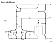
It's a bit odd but intended to be a single-supply fixed gain block, probably intended to be used with input a.c. coupling, with automatic half-supply centering of the output. It's not an op amp per se despite the labeling of - and + inputs, both of which are fairly high impedance. If you lose the left-hand Darlington stage and substitute another bias source, and figure out another way to center the output voltage, you also lose one gain path through the current mirror. But you are left with a current-mode feedback path via the resistors to the right-hand Darlington emitter, with its collector driving the so-called VAS stage which drives the quasi-complementary output stage. I gather from the typography that this is some ancient National part.
You could with due attention to d.c. biasing use the right-hand Darlington emitter as a CFA-style inverting input. Things won't be all that fast, in part because it's likely that the PNP devices are slow dogs of that era.
EDIT: Ah should have recognized it --- it's the LM386, which I actually used once. http://www.ti.com/lit/ds/symlink/lm386.pdf
(for the schematic see post 77654; I can't lift it with sufficient resolution)Is this a CFA ?
It's a bit odd but intended to be a single-supply fixed gain block, probably intended to be used with input a.c. coupling, with automatic half-supply centering of the output. It's not an op amp per se despite the labeling of - and + inputs, both of which are fairly high impedance. If you lose the left-hand Darlington stage and substitute another bias source, and figure out another way to center the output voltage, you also lose one gain path through the current mirror. But you are left with a current-mode feedback path via the resistors to the right-hand Darlington emitter, with its collector driving the so-called VAS stage which drives the quasi-complementary output stage. I gather from the typography that this is some ancient National part.
You could with due attention to d.c. biasing use the right-hand Darlington emitter as a CFA-style inverting input. Things won't be all that fast, in part because it's likely that the PNP devices are slow dogs of that era.
EDIT: Ah should have recognized it --- it's the LM386, which I actually used once. http://www.ti.com/lit/ds/symlink/lm386.pdf
Last edited:
In other words, parameters count, not semantic.
Yes, parameters count. Which is why I measure when ever I can.
THx-RNMarsh
(for the schematic see post 77654; I can't lift it with sufficient resolution)
EDIT: Ah should have recognized it --- it's the LM386, which I actually used once. http://www.ti.com/lit/ds/symlink/lm386.pdf
Thanks ......... But is it a CFA ? ...... Even if not declared such ......
I ask because the built in feedback goes back to the emitter (s) of the
input which to my simplicity denotes current feedback.
Usually the - (base) input of the front-end is not used for feedback .
I really hate those.
They work best at <HF freqs and low Z circuits. High Z values will cause a lot of grief.... affects of cross-talk, stray L and C come into play. My experimental circuit did not use values higher than 1K max.
One thing I do is place a single-sided pcb under the prototyping pcb and/or bread-board and ground it at appropriate place. It helps.
Otherwise, there are prototyping pcb with pads all over it to mount parts; TH or smd and plane on other side. But, I dont need that 99% of the time for audio.
THx-RNMarsh
Last edited:
Still not seen a good reason for such high bandwidth parts. Linear to 100KHz is not a problem, but needing good CMRR from an instrumentation front end at 250KHz when you are in a region where you can passively filter noise and grot seems a little extreme even for this place!
Thanks ......... But is it a CFA ? ...... Even if not declared such ......
I ask because the built in feedback goes back to the emitter (s) of the
input which to my simplicity denotes current feedback.
Usually the - (base) input of the front-end is not used for feedback .
Yes it's a CFA as far as the internal resistive feedback works, and viewing the right-hand input device as emitter as inverting input and base as non-inverting input. It lacks the symmetrical complementary arrangements with complementary current mirror stages of the typical CF op amps. And it has a sort-of extra emitter input on the left that adds to the closed-loop gain, as well as providing an inverting high-Z input at that compound transistor's base. This stage facilitates the centering of the output voltage via the input from the two 15k resistors from the + power supply rail.
It's an interesting approach, and it is probably a variant on something more symmetrical in the Senani et al. book.
Oddly, I found a discussion in the 1976 National Audio Handbook of it and a higher-power fixed-gain power amp, the LM380, with an incorrect explanation of the voltage gain at inverting and non-inverting inputs. There is a small difference in gains but not as much as stated, or following the formula offered. A closer, albeit still-simplified analysis is needed that accounts for all of the currents that flow when a given base is driven.
Thanks for bringing that up.
Still not seen a good reason for such high bandwidth parts. Linear to 100KHz is not a problem, but needing good CMRR from an instrumentation front end at 250KHz when you are in a region where you can passively filter noise and grot seems a little extreme even for this place!
Who are you replying to here, Bill?
> Thanks for bringing that up.
Here's a clearer schematic .
That whole series of LM??
audio amp DIP's sound nice
to me ............
It would appear that the ' mode '
differs inverting or non .....
???
Here's a clearer schematic .
That whole series of LM??
audio amp DIP's sound nice
to me ............
It would appear that the ' mode '
differs inverting or non .....
???
Attachments
Last edited:
Who are you replying to here, Bill?
RNM. Still not clear why such huge bandwidth parts being tested for linearity up to 100KHz, other than 'cos I can' which is perfectly valid 🙂
Thats marketing.... it is a CFA with a buffer on the low Z CFA input to make that port high Z also.
THx-RNMarsh
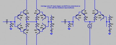
The same could be said of an LTP, except it's just the non-complimentary equivalent.
EDIT: Illustration to make it apparent.
Attachments
Last edited:
Completely incorrect. Either you believe this, in which case you have some learning to do, or you know it's incorrect and you're just trolling.
It really is a sad thing to see things like this from someone with experience and background.
A complete lack of tact. 🙁
RNM. Still not clear why such huge bandwidth parts being tested for linearity up to 100KHz, other than 'cos I can' which is perfectly valid 🙂
The huge BW wasnt needed and I made the circuits' amps 'only' go to 1.2MHz. But, I was also curious as to the THD profile at and above 20KHz to >100KHz of a 4500 v/usec SR part.
if you have a VFA which has rising non-linearity at AF and above, IMO you might want to use a LPF on the input to reduce possibility of noise/distortion falling into the AF region. I've already been over that ground, earlier.
THx-RNMarsh
Last edited:
A complete lack of tact. 🙁
How old is this quote? Nothing tactless here IMHO.
You guys have to get over this CFA vs. VFA fetish, really it leads nowhere.
Last edited:
- Status
- Not open for further replies.
- Home
- Member Areas
- The Lounge
- John Curl's Blowtorch preamplifier part II