But not the mostly constant bandwidth with gain.
After all these years we still belabor these points, depressing in a way.
I posted up a sim of an H- bridge amp 3 or 4 years ago on the forum. My conclusion was, after plotting the loop gain vs f, that it was a CFA. However, since the feedback Port is high Z, the semi industry decided to call it a VFA.
It's an interesting topology and it does solve the feedback resistor dissipation issue that one finds in power CFA's. However, it comes at the expense of additional complexity.
It's an interesting topology and it does solve the feedback resistor dissipation issue that one finds in power CFA's. However, it comes at the expense of additional complexity.
My conclusion was, after plotting the loop gain vs f, that it was a CFA.
It can't be a CFA, since it does not follow all of your very own "two tests and two pointers method".
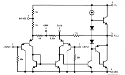
I wonder if anybody not seeing that over simplified schematic in the datasheet would recognize the LM7171 as having anything to do with a CFA topology. Hint: unlikely.
Quiz: based on the datasheet information, is the TI THS6031 a CFA or a VFA?
Yes it`s an old circuit, never mind that, LT1363 one very good sounding chip (even better with the OPS biased to class A).
(and a bottle of Pole Roger for Monsieur)
Mr Bond prefers the 1955 Bollinger.
Other than for Lolz is there any good reason anyone can think of for using 200MHz parts in audio?
Knee Jerk reaction: maybe in a I-V converter? GBW helps out there a fair bit, IIRC, and iff you can keep it from running away from you.
Otherwise, really fast "output stages" for composites are much easier to design with.
Not your run of the mill applications, though.
Otherwise, really fast "output stages" for composites are much easier to design with.
Not your run of the mill applications, though.
Expect to see more of these.
THx-RNMarsh/QUOTE]
In the context that I have been talking about... expect to see more of these circuits in PA's. Dadod's is an example of buffer used with a CFA PA to make two high Z inputs.
When I used the -7171 it wasnt for a PA... but for a Bal/unbal converter.
The distortion at HF is very low.... .01% at 50KHz in my bread-board.
THx-RNMarsh
Last edited:
Actually -7171 is quite a bit better than .01% at 50KHz. Using a better source, at 110KHz it is about .003% THD.
-RNM

-RNM
As I remarked previously in various posts and on my website, CFA's have specific electrical characteristics (as do VFA's) and those were captured in the tests and pointers I proposed. You can define the type of amplifier purely but its topology or you can include the behavioral characteristics as well - which is what I tried to do with the tests and pointers.
On the 'H' bridge amplifier, both the + and - inputs are high Z. But the response is more representative of a CFA - the bandwidth is constant despite changes in closed loop gain. The bridge tie resistor sets the peak current into the TIS, somewhat emulating the feedback resistor function in the CFA.
I have noted that it's classified as a VFA and so be it. With more advanced comp schemes, the line between the two is rather blurred - and especially so with high OL CFA's where with basic MC you have to resort to pole splitting to get it stable. Of course, you can use more advanced comp schemes, but I am merely illustrating a point here.
It's indeed a pity that this subject (VFA vs CFA) seems to generate so much passion and I would even say hatred (go back and read some of the posts in that thread - quite shocking). It's no wonder the thread was closed down.
It's a damn circuit guys - get over it.
Last edited:
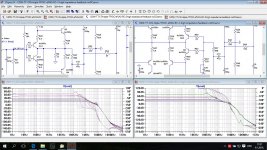
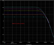
This plot shows two different FB implementation for the same amp.
Whit the low impedance FB input it suppose to be called CFA but gain-bandwidth product looks constant and that is VFA characteristic. With added buffer before FB low impedance input does not change much, it looks the same for me, but it is called VFA now. Both amps have very high Slew Rate.
To generate the plots Rf was stepped.
Any comments?
Damir
Attachments
I'm a little afraid of the "nervous" tendancy of the Super Pair ( and Diamond as well).You something lose and something gain. In mine CFA configuration distortion is going down with lower feedback network impedance but it's not good to go to low because the power loss and dissipation on the feedback resistors. I use 22R/560R as lowest value. When I added a buffer to the low impedance feedback input I've got even lower distortion then without, at least in simulation. I think there two reasons for that, very low buffer it self distortion (supper pair emitter follower) and even lower then 22R buffer output impedance. That is just simulation, but I hope as with other my simulations not far from reality. Don't be afraid to think out of the box and you could be surprised.
With that buffer in place you still can use quite low impedance feedback network.
And that opens other possibility I can't explain yet.
Anyway, worth a try. And may-be a good idea too in A VFA, that suffer usually from the high impedance of the feedback path when we want to balance the two inputs impedance.
Btw, thinking out of the box is my life's rule ;-)
Last edited:
To get in the same time full bandwidth and high gain in OLG ? I'm not satisfied by the speed of the actual devices.Other than for Lolz is there any good reason anyone can think of for using 200MHz parts in audio?
As I remarked previously in various posts and on my website, CFA's have specific electrical characteristics (as do VFA's) and those were captured in the tests and pointers I proposed. You can define the type of amplifier purely but its topology or you can include the behavioral characteristics as well - which is what I tried to do with the tests and pointers.
On the 'H' bridge amplifier, both the + and - inputs are high Z. But the response is more representative of a CFA - the bandwidth is constant despite changes in closed loop gain. The bridge tie resistor sets the peak current into the TIS, somewhat emulating the feedback resistor function in the CFA.
It's a damn circuit guys - get over it.
😎🙂
You are one of the few people who get it right. THx for your effort to clarify CFA. I understand the essence of the 'discussion' is on your web site for all to read. From now on, I'll just point to your site and not regenerate the discussion.
There are many books on the subject... some of the best I pointed to in the CFA discussion. I hope you would ref to them also on your site. [Maybe arguing with the authors of the books would be better than doing it here.]
BTW - some of the worst attempts seen were/are on the web sites marketing info of the mfr of CFA devices. LT in their App Info gives a fair account of the basic block diagram and one paragraph description of a seemingly complex issue for some stuck on voltage operated circuits.
-RM
Last edited:
Other than for Lolz is there any good reason anyone can think of for using 200MHz parts in audio?
Of course. The old "high open loop bandwidth" and the "100's of V/uS" tunes will not die anytime soon within the fashion audio kabbalah.
😎🙂
You are one of the few people who get it right. THx for your effort to clarify CFA. I understand the essence of the 'discussion' is on your web site for all to read. From now on, I'll just point to your site and not regenerate the discussion.
I can feel the love in the air

The only small problem is that the LM7171 doesn't walk or quack as a CFA. Of course, you can make it to, by popular vote 😀.
Attachments
I'm not going there Waly. The description of what a CFA is has been done else where in scholarly publications a long time ago. Done.
In Applications, the 7171 (and other P/N) with the buffered input is the best of both worlds. Because of its linearity at HF, I think it can help with some situations... like HF getting into the audio circuits... via PS or I/O. It's linearity above audio has practical affects in the field (audio record/playback systems). In the field, we can be exposed to HF in many ways... unlike isolated bench testing or sim. It reduces another hidden variable.
It is an additional reason why CFA (with or without buffered input) get that last 1% of performance in practice.
Let's move on, pls.
THx-RNMarsh
Last edited:
- Status
- Not open for further replies.
- Home
- Member Areas
- The Lounge
- John Curl's Blowtorch preamplifier part II