I was the Alesis Service Center Admin. in the pre-bankruptcy Alesis. I have had a ML9600 when it was a current product and I still have it. Trust me, it still works just the same now as it did when there was technical support.One reason not to get involved with the ML9600 is that according to Alesis and a number of Alesis authorized dealers, the ML9600 is obsolete. For example this is the Alesis web page of obsolete products:
Legacy Products
As far as its feature set goes, the obvious comparison is with one of the many computer audio interfaces that exploit the hardware that many people already have, yielding superior flexibility at a far lower cost.
Just for grins:
12 reasons why hi-res audio will never go mainstream | DAR__KO
Higher sampling rate decreases requirements to reconstruction filters, for the simple reason, there is no audio spectral content recorded close to 48 kHz (96kHz/2). So the demand for higher sampling rate is definitely correct from the view of real implementation.
What causes the missing odd and why the train of harmonics ends in this way?
George
The lines behind Fs/2 are mirror images so it depends on their frequency. The train of harmonics ends this way depending on properties of reconstruction filter.
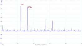
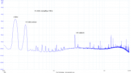
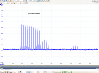
Another example of really poor reconstruction filter. Measured signal is 100Hz (44.1kHz) square at soundcard DAC analog output. Measuring sampling rate is 6.25MHz. The filter may look "OK" visually (no pre-ringing), but as a result there is a train of mirror images.
Attachments

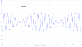
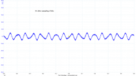
21kHz sine with the same filter. See mirrors and modulation.
Digital is almost perfect - in theory. But not in a real world implementations. Maybe a lot of these issues is avoided with 24/96 in new pocket audio.
Digital is almost perfect - in theory. But not in a real world implementations. Maybe a lot of these issues is avoided with 24/96 in new pocket audio.
Attachments
I am sorry, but you did not get it, maybe I was not explaining enough.
1) it is not a result of graphics and it is no simulation. It is an output of sound card digitized with a very fast digitizer. The "modulation" in time domain is another view to twin-tone in frequency domain. The twin-tone is a result of mirror image spectral line, which is 44.1 - 21.5 = 22.6 kHz. This is a result of not enough high steepness of the reconstruction filter. Please check the attached images.
2) everything you wrote about filters is OK, but it is a pure theory. I have measured dozens of CD players and sound cards and I am showing an usual and common behavior of real implementations.
3) it is an Oversampling DAC, quite up to date (AK).
This neatly demonstrates why avoiding the output filter, or not making it steep enough in order to minimize ringing simply leaves one with Nyqvist related problems. Better to go for 24/192, accept the slightly higher noise floor and be done with it.
(Thorsten Lösch, Mr. Russell)
Ahh - got it.
(He loves his multi- bit DAC's with minimal or no output filters.)
The lines behind Fs/2 are mirror images so it depends on their frequency. The train of harmonics ends this way depending on properties of reconstruction filter.
OK Pavel, sorry for bothering you.
I thought that what you had shown was the FFT of the test waveform (but it was the FFT of what came out of the playback)
George
No problems George, it is the playback, I am really too brief in my posts and I prefer images over explanations.
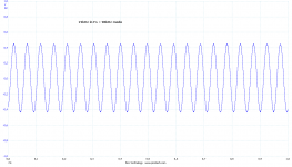
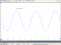
Reconstruction in real world is really an issue. Last one, it is a small signal 17kHz (i.e. audio signal) in 44.1kHz sampling. The reconstruction filter is very poor (but no pre-ringing!!! 😀 😀) and also please note HF interferences in MHz, at the analog output.
As said several times, let's go higher sampling rates to have enough margin for audio band signals.
Someone might say "no problem, inaudible". But please think about intermodulation products in tweeters and I can guarantee these examples will and do create audible intermodulation products in tweeters.
Attachments
Last edited:
It is that real music hasn’t much close to 20kHz that saves the game.
(watch the flame war now)
George
(watch the flame war now)
George
Hi,
This, IMO, is another manifestation starting to show the affect of approaching the 'Gibbs' condition.
Not really - the explanation for the apparent modulation of signals whose frequency are very close to the Nyquist frequency comes out of modulation theory. Basically we are moving from AM to SSB.
Not really - the explanation for the apparent modulation of signals whose frequency are very close to the Nyquist frequency comes out of modulation theory. Basically we are moving from AM to SSB.
Once again - the reason of "modulation" is a mirror image, F(sampling) - F(signal). Close to Fs/2 signals, reconstruction non-ideal brickwall is unable to avoid mirrors. Mirror makes a twin-tone (similar to 19+20kHz CCIF test tone) and this causes "modulation" with frequency F(signal) - F(mirror).
Once again - the reason of "modulation" is a mirror image, F(sampling) - F(signal). Close to Fs/2 signals, reconstruction non-ideal brickwall is unable to avoid mirrors. Mirror makes a twin-tone (similar to 19+20kHz CCIF test tone) and this causes "modulation" with frequency F(signal) - F(mirror).
Pavel,
Time for you to do a book. Jan will pay for it.
All,
The 44.1 sample rate was originally picked to allow the data to be written to the VCRs of the day. The physical size was correctly reported.
I thought I was the only one at the time who though the sample rate was too low. At that time the A/D converters that were state of the art were really a composite of a 9 bit with a 7 bit second stage. The very first units were made of discrete components including matched and trimmed Allen Bradley CC resistors. Later Sony copied the design into a single chip. The best results I ever got from that chip was a bit more than 14 bits. That was enough for the folks doing research at the time. Moving from 11-12 bits to 14-1/2 showed no improvement in their results.
Of course with the then state of the art one megabit Ethernet file transfer was so slow it was faster to move drives.
Pavel: a naive question if you allow me: what happens to the 21khz sinewave if you feed the 44.1khz signal to a sample rate converter in front of the DAC ?
I am sorry, but you did not get it, maybe I was not explaining enough.
I believe I got it, hehe😉. That is a problem of interpretation and communication only. Any interpretation based on spectral is a pure theory, because the "spectrum" doesn't exist in reality, this is only an other way to describe the signal, which is primarily described by its time run. The "mirror" component shown is an inevitable product of sampling at 44.1 kHz. If reconstructed properly, this component will not be present in the resulting signal. This is - according the theory - possible only if an ideal brickwall filter is used, or, more generally, an filter achieving infinitely big attenuation above certain frequency being lower than a half of the sampling frequency. In fact you said this. If something like "modulation" or "mirror" is observed, than this is a consequence of the imperfection of the filter. You did say it, too. And, this match with the theory exactly, if applied properly. The only difference between our interpretations is that I say the modulation or mirrors described in the digital domain are the inevitable product of sampling, so they are artifacts, existing in digital domain only, which existence can be proved basing on the certain interpretation of the signal structure only and which are not returned into analog domain if reconstructed properly.
The fundamental problem is the all real signals are continuous, the digitalization is an purely analog process and the "digital signal" is a mathematical fiction in fact, a subject of certain interpretation only. No doubt this interpretation is very useful, but it is necessary to bear in mind its limits.

Last edited:
Of course with the then state of the art one megabit Ethernet file transfer was so slow it was faster to move drives.
Ethernet was 10Mb/s back then. I doubt there were hot-pluggable drives, so transferring over Ethernet was always faster than moving media around, especially given the speed of writeable media like tape.
Ethernet was 10Mb/s back then. I doubt there were hot-pluggable drives, so transferring over Ethernet was always faster than moving media around, especially given the speed of writeable media like tape.
No, it was over coax and 1 megabit, although it really was just before what is now known as "thicknet" which was 10 megabit. Used a special variant of RG8 cable. Vampire taps didn't come in until a bit latter.
The usage made it terribly slow and interchangeable hard drives were common on the original Xerox Alto work stations and similar 14" hard drives.
- Status
- Not open for further replies.
- Home
- Member Areas
- The Lounge
- John Curl's Blowtorch preamplifier part II