Amp work fine with litle rounded 10kHz square way no need to changes.
Regards
This is what I was hoping I could explain to Terry with the resulting scope traces from his work. The corner edges of the squarewave at high frequency has appeared to be noticeably rounded and a bit large at 10khz (my assumption). I do think it is called treble cut. (depending on the volt/div and baseline of the scope setting). My knowledge is that some amps shows very little treble cut at 10khz given the same amplitude I do think amp bandwith dictates this response. However 5hz to 50khz bandwith as you have posted previously is pretty good.
Correct me if I'm wrong.
Last edited:
Completely confusing that Apex has all these different amps in the same Thread as "100W Ultimate Fidelity Amplifier".This thread always confused me.😕
So many amplifiers in one thread...when someone say for one amplifier other one answer for another😕
That's why I had to ask which schematic to which he was referring for those changed capacitors.
It would be far better if Apex arranged with the Moderators to split this confusing Thread into one variety for each new Thread. Each sch would have the correct name in the title box and that would also be the name in the Thread title.
Apex please sort this mess !
This floating first stage amp is not new topology.Ground is not strange but floating rail for OP amp to drive outputs direct without VAS.
This is new topology in DIY, Terry made very first prototype.
It is in quite a few previous designs. The output is bootstrapped to the first stage supply rails and drives the first stage so that the output remains within it's supply rails.
It's new to this Thread and deserves a SEPARATE Thread to discuss the topology.
That's a disaster waiting to happen.I can't say about sound difference. I will try to get around to that on Saturday or Sunday. I prefer to build the lateral. Less parts and no thermal concerns.
A couple other things of note. I tried TL072, NE5532 and LM4562. They all exhibit the same "notch" in the square wave.
Also, this amp is highly sensitive to an open input. Without something plugged in or the input shorted the amp oscillates instantly.
This should never have been presented as a working proposal to the Membership.
It could instead have been presented as a topic for discussion to iron out these "bugs" before it gets onto the recommended list.
APEX did not said that it is completly new topology,but new in DIY.
Opamp based amplifiers use OLD topology (LM417, LM318). In DIY, they are not new either, but probably not common because this topology tends to oscillate (opamp or output transistor roll-off is not proper here).
What is NEW here is the design. It is not a proven design yet. Even commercial amplifiers using this topology are not save without speaker protection. So new builders should be made aware of this.
no one said it is proven,but work in progress and anybody that followed this thread can conclude that. Terry is working on it as we can see,there are some troubles but hey,how many amplifiers have been made directly from paper into a working device without adjusting and fixing some bugs? i am not really the one that has many rights to claim anything, but I said it anyway...
finally, let's not do this amplifier - or let's do it. it is on each of us to decide. if there will be to many fails,no one will do it again...
finally, let's not do this amplifier - or let's do it. it is on each of us to decide. if there will be to many fails,no one will do it again...
It's not new in DIY.APEX did not said that it is completly new topology,but new in DIY.
It is old technology.
As I said, it has been used before and is shown in quite a few designs here in the DIYaudio Forum.
That is even more reason that it should not be IN THIS THREAD.no one said it is proven,but work in progress and anybody that followed this thread can conclude that. ..............
It deserves it's own Thread with it's own title.
It's not new in DIY.
It is old technology.
As I said, it has been used before and is shown in quite a few designs here in the DIYaudio Forum.
Can you share links for this few designs here in the DIYaudio Forum?
Also, this amp is highly sensitive to an open input. Without something plugged in or the input shorted the amp oscillates instantly.
Still4, do you look for that osc freq without input connect/open?
Amplitude, freq @ OUT with 8R0 load?
----------------------------------------------
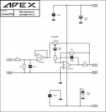
SCH: #5778
Step-by-step:
-Put additional 18K-22K // to the input, from SigIN to SigGND.
Also // 100-220pF directly on the input connector (RCA), for RF filter,
reason: prototype without chassis/shield, long input connect ...etc =RF antenna , with strong AM radio in in the immediate vicinity
-Put additional 10pF-22pF // R20 (15K), @ NFB
-Put additional 100-220pF /100VDC from star point (R15, R4, R8, C2, C3) to GND, this will reduce strongly SR, but stabilising the amp,
put it smaller you can with no output osc
LP
Dragan
Last edited:
This should never have been presented as a working proposal to the Membership.
Prototyping in progres, thanks to Terry!
Opamp based amplifiers use OLD topology (LM417, LM318). In DIY, they are not new either,
but probably not common because this topology tends to oscillate
(opamp or output transistor roll-off is not proper here).
What is NEW here is the design. It is not a proven design yet.
Even commercial amplifiers using this topology are not save without speaker protection.
So new builders should be made aware of this.
Yes and yes and yes!
Thanks Jay!
Bootstraped flying supply refferenced to OUTPUT for Op-amp VAS with to much gain and poor BW.
If there is no tends for OSC is certainly somethings wrong with that powerfull oscilator... 🙂
LP
Dragan
That is even more reason that it should not be IN THIS THREAD.
It deserves it's own Thread with it's own title.
Yes, completely correct,
I agree with you.
LP
Dragan
I don't keep a register/index of designs.
In post #5820 sajti share schematic of commercial amplifier MC2 E15 with this topology, I want to see any diy amp with similar circuit.

Merry Christmas friends.
I guess everyone has their own preferences. As a "builder/tester" I have two favorite threads. This one and the Slewmaster thread. If each one of Mile's amps had its own thread they would have fallen off the the page long ago and be very difficult to find and search. This way, if you know it was an APEX Axxxxxx amp, you can come here and find the info you seek. There has been a plethora of new designs to build. I have built most of them and they all sound wonderful and won't break the bank to build them.
As far as the A2, Mile was clear when he posted the design that it was for playing around with in sim form. I was bored so I tried my hand at drawing a layout so I could try building it. It has been fun trying to get it working and hopefully give some level of enjoyment for those following along.
When I say oscillate I meant the current draw goes through the roof and I am sure it would self destruct if not shut down. With the input shorted or something plugged into it it is tame. I will try some of the suggestions.Still4, do you look for that osc freq without input connect/open?
Amplitude, freq @ OUT with 8R0 load?
Merry Christmas friends.
When I say oscillate I meant the current draw goes through the roof and I am sure it would self destruct if not shut down. With the input shorted or something plugged into it it is tame. I will try some of the suggestions.
This amp need preamp or buffer on input, it can not work only with pot, use this preamp for A2 or any other amp.
Preamp use standard psu +/-15V ref to gnd not to amp out.
Attachments
Last edited:
Merry Christmas friends.
As far as the A2, Mile was clear when he posted the design that it was for playing around with in sim form.
I was bored so I tried my hand at drawing a layout so I could try building it.
It has been fun trying to get it working and hopefully give some level of enjoyment for those following along.
When I say oscillate I meant the current draw goes through the roof and I am sure it would self destruct if not shut down.
With the input shorted or something plugged into it it is tame. I will try some of the suggestions.
Merry Christmas friends...
-----------------------------
-Thanks Terry,
-Smart decision!!! 🙂
tray to look at that Output oscillations with 8R0 load and with open input.
Use some 15-33R/several W resistors on both rails (current limiters) and test the amp only briefly, with proposed suggestions, but one at the time!
also look at temp of output Zobel network resistor (R2 10R/2W).
You can use also 60-100W light bulb on primary side to strongly limiting amp destructive currents (for testing purpose).
Testing only with max 15-20Vp-p output amplitude, otherwise the limiters will perform strange scope readings. 🙂
With known OSC freq we can put another notch in NFB (small R+suitable C).
Like:
R=390R
Measured from scope we determine 175KHz osc (if there is only one freq, but can be superimposed several freq and lot of their higher harmonics...))
C = 1 / (2*PI*390R*175K) = 2,33nF, take 2,2-2,7nF
PI=3,14
Solder on pins R19 // (390R+2,2nF)
LP
Dragan
Last edited:
- Home
- Amplifiers
- Solid State
- 100W Ultimate Fidelity Amplifier