Found that the left amplifier is not working correctly, there's a noise floor at -50 dB and heavy distortion when I play anything louder than 1 W.😱Is the distorsion level raised or is it -30dB?
//
Guess I ruined it when I was on my last tour.
No wonder I didn't like to listen to music after that.
So just forget all the UMIK-measurements (that were made with that amplifier) above.
Hopefully I can fix the amplifier soon or I'll redo the measurements with the other amplifier.
hmm my laptop makes noticeable noises to. prob from the adapter. im wondering if this comes back in these measurements as well?
hmm so you can measure thd with a dac with high noise floor but cant with amp with high noise floor ? am i missing something. it does not compare the output to input anywhere how does he now what comes from what? my output is not calibrated noir is yours since you use umic. calbrating with the loopback will give some result but. it is then calbrated for the line in and out. :9 so corrections might be for the line the line in if aplied. there is no way telling it was the output at fault or the imput.
Green is the Output DAC signal looped directly to the ADC input.
Red is the Output DAC signal feeding the Right Amplifier, the output from the amplifier is then via a dummy load and a voltage divider input to the ADC input.
Blue is the Output DAC signal feeding the Left Amplifier, the output from the amplifier is then via a dummy load and a voltage divider input to the ADC input.

With higher input to the left amplifier its distortion gets even worse.
Red is the Output DAC signal feeding the Right Amplifier, the output from the amplifier is then via a dummy load and a voltage divider input to the ADC input.
Blue is the Output DAC signal feeding the Left Amplifier, the output from the amplifier is then via a dummy load and a voltage divider input to the ADC input.
With higher input to the left amplifier its distortion gets even worse.
oh jesus, thats indeed allot compared to the other. well stupid thing is i could do a DAC to adc loop but i then measure mey line input and line output. it has nothign to do with the mic on the USB input. so i still wont know if the line in sucks or the line out. 🙂 or the UMIK 🙂
my laptop does not even have line in just mic. but still i need to calibrate it if its straight i at least now the curve is about right.
my laptop does not even have line in just mic. but still i need to calibrate it if its straight i at least now the curve is about right.
Last edited:
Hi Wrinex, I hope that you have noted that I now have great use of the VHB tape I bought a couple of months ago.
Oh nooo , i missed that one what did you do with it ?? i only have 50 euro worth of the thicker VHB 🙂 that eap was a fail 🙂 although it did work as an eap but as a speaker not so much 🙂 at least not yet.
hmm so you can measure thd with a dac with high noise floor but cant with amp with high noise floor ? am i missing something. it does not compare the output to input anywhere how does he now what comes from what? my output is not calibrated noir is yours since you use umic. calbrating with the loopback will give some result but. it is then calbrated for the line in and out. :9 so corrections might be for the line the line in if aplied. there is no way telling it was the output at fault or the imput.
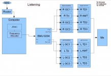
My setup is only PC with software, USB DAC, amplifier and loudspeaker.
The USB DAC has two ADC channels as well.
These are the different setups:
Listening:
An externally hosted image should be here but it was not working when we last tested it.
DAC/ADC loop:
An externally hosted image should be here but it was not working when we last tested it.
Amplifier measurements:
An externally hosted image should be here but it was not working when we last tested it.
Loudspeaker measurements with WM61a:
An externally hosted image should be here but it was not working when we last tested it.
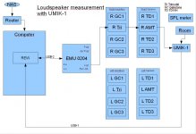
Loudspeaker measurements with UMIK-1:
An externally hosted image should be here but it was not working when we last tested it.
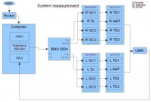
System measurements including crossover and PEQ:
An externally hosted image should be here but it was not working when we last tested it.
I have used it in folding tools as it is heat resistance and also for fastening the membrane to the frame.Oh nooo , i missed that one what did you do with it ?? i only have 50 euro worth of the thicker VHB 🙂 that eap was a fail 🙂 although it did work as an eap but as a speaker not so much 🙂 at least not yet.
DAC/ADC loop:
I've had relays as protection for my ribbons between the amplifier output and the ribbons.
The relays looked like this:
It was the relays that caused the high distortion levels!
And the good news is that the AMTs is not that sensitive so I don't need any protective relays.
So this is how the two Trimodal amplifiers measure (the ones that I use for the AMTs):
Apart from the usual distortion from the 50 Hz harmonics, the distortion levels are below -100 dB.
An externally hosted image should be here but it was not working when we last tested it.
I've had relays as protection for my ribbons between the amplifier output and the ribbons.
The relays looked like this:
An externally hosted image should be here but it was not working when we last tested it.
It was the relays that caused the high distortion levels!
And the good news is that the AMTs is not that sensitive so I don't need any protective relays.
So this is how the two Trimodal amplifiers measure (the ones that I use for the AMTs):
An externally hosted image should be here but it was not working when we last tested it.
An externally hosted image should be here but it was not working when we last tested it.
Apart from the usual distortion from the 50 Hz harmonics, the distortion levels are below -100 dB.
Seems like the only way nowadays is to actually upload the pictures to diyaudio.ohoh pictures dont work 🙁
I tried for several hours with Google Photo, Goggle+ and Dropbox.
All of of them worked before so I guess that the link addresses meta data have changed and that the current forum software cannot deal with them.
So I finally cave in and uploaded the pictures to diyaudio...
My setup is only PC with software, USB DAC, amplifier and loudspeaker.
The USB DAC has two ADC channels as well.
These are the different setups:
Listening:

DAC/ADC loop:

Amplifier measurements:

Loudspeaker measurements with WM61a:

Loudspeaker measurements with UMIK-1:

System measurements including crossover and PEQ:

I hope that you both get the pictures and get the picture!
My setup is only PC with software, USB DAC, amplifier and loudspeaker.
The USB DAC has two ADC channels as well.
These are the different setups:
Listening:
DAC/ADC loop:
Amplifier measurements:
Loudspeaker measurements with WM61a:
Loudspeaker measurements with UMIK-1:
System measurements including crossover and PEQ:
I hope that you both get the pictures and get the picture!
Attachments
-
 MWSnap 2015-12-16, 13_38_41.jpg95 KB · Views: 400
 -
 MWSnap 2015-12-16, 13_38_56.jpg85 KB · Views: 384
 -
 MWSnap 2015-12-16, 13_39_09.jpg95.5 KB · Views: 389
 -
 MWSnap 2015-12-16, 13_39_21.jpg98.8 KB · Views: 396
 -
 MWSnap 2015-12-16, 13_39_35.jpg101.7 KB · Views: 389
 -
 MWSnap 2015-12-16, 13_48_50.jpg99.2 KB · Views: 372
So I have started to use REW since Holm is not supporting Windows 10.
Good is that with the calibrated UMIK, I'll get all microphone measurements with the correct SPL!
Note that all distortion levels are in dBr, that is relative to the fundamental. Just like Holm did.
So you should not do any math, subtracting the levels.
DAC/ADC loop:

I've had relays as protection for my ribbons between the amplifier output and the ribbons.
The relays looked like this:

It was the relays that caused the high distortion levels!
And the good news is that the AMTs is not that sensitive so I don't need any protective relays.
So this is how the two Trimodal amplifiers measure at 22 W (the ones that I use for the AMTs):


Apart from the usual distortion from the 50 Hz harmonics, the distortion levels are below -100 dB.
I think that is a really sound start.
Good is that with the calibrated UMIK, I'll get all microphone measurements with the correct SPL!
Note that all distortion levels are in dBr, that is relative to the fundamental. Just like Holm did.
So you should not do any math, subtracting the levels.
DAC/ADC loop:
I've had relays as protection for my ribbons between the amplifier output and the ribbons.
The relays looked like this:
It was the relays that caused the high distortion levels!
And the good news is that the AMTs is not that sensitive so I don't need any protective relays.
So this is how the two Trimodal amplifiers measure at 22 W (the ones that I use for the AMTs):
Apart from the usual distortion from the 50 Hz harmonics, the distortion levels are below -100 dB.
I think that is a really sound start.
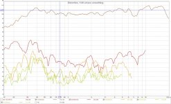
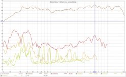
The first calibrated measurements using UMIK-1 together with REW for the membranes in post #562:

Left AMT:

Right AMT:

Pretty much the same levels as with Holm, but now I know that it is the actual SPL levels.
Note, again, that the distortion levels are in dBr, that is relative to the fundamental.
For instance, at 2,3 kHz for the Left AMT we have 103 dB SPL for 1 W at 50 cm, 2nd HD is -53,6 dBr, 3th HD is -64 dBr.
The SPL is within +7- 5 dB from 280 Hz to 18,74 kHz with a smaller dip at 1070 kHz.
The 2nd HD level is somewhat high at 6,0 kHz, but then the SPL has a dip at 12,0 kHz.
So something that is 29 mm wide or deep is vibrating?
The work continues...
Left AMT:
Right AMT:
Pretty much the same levels as with Holm, but now I know that it is the actual SPL levels.
Note, again, that the distortion levels are in dBr, that is relative to the fundamental.
For instance, at 2,3 kHz for the Left AMT we have 103 dB SPL for 1 W at 50 cm, 2nd HD is -53,6 dBr, 3th HD is -64 dBr.
The SPL is within +7- 5 dB from 280 Hz to 18,74 kHz with a smaller dip at 1070 kHz.
The 2nd HD level is somewhat high at 6,0 kHz, but then the SPL has a dip at 12,0 kHz.
So something that is 29 mm wide or deep is vibrating?
The work continues...
Attachments
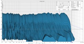
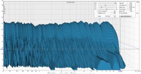
Need help with Water fall
I got Water fall generated from one of the 50 cm measurements above.
Without CSD:

With CSD:

How shall I interpret them?
Is there for example an induced vibration in some mechanics at 7 kHz or some multiple of its wavelength?
I got Water fall generated from one of the 50 cm measurements above.
Without CSD:
With CSD:
How shall I interpret them?
Is there for example an induced vibration in some mechanics at 7 kHz or some multiple of its wavelength?
Attachments
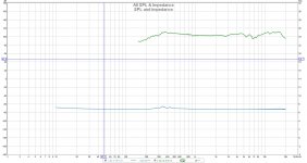
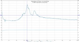
Impedance
Also made an impedance measurement, first plot is a SPL and impedance overlay:

Second plot is a close up of the impedance around the resonance frequency:

Note that the phase was 0 degress across the whole spektrum.
Also made an impedance measurement, first plot is a SPL and impedance overlay:
Second plot is a close up of the impedance around the resonance frequency:
Note that the phase was 0 degress across the whole spektrum.
Attachments
Close up videos
I finally made some close up videos on the AMT's excursions.
Frequency is 150 Hz, first at a descent non distorting level and then higher and higher.
Recording frame rate is 600 fps, how you will see it depends on your viewer; 24, 25 or 29.97 fps I guess.
I think what is happening at the higher excursions is of interest, high distortion of course but what is really happening?
Hint: Hit the space bar or pause in your viewer; there should be 4 frames per end to end movement.
https://youtu.be/-WPtQf-H8Eg
https://youtu.be/aQmPvTh4XoI
https://youtu.be/YMGXSV7o_iA
https://youtu.be/L0Tyd577Cgw
https://youtu.be/QtCAp_PBU34
https://youtu.be/N2CZ40LDKMA
Last edited:
Nice dude !!! Good information . You say umik is standard calibrated for rew ?there is still a mixer/record level for the thing. Where does it supposed to be all depends on the smolifier ofc so what I'd calibrated
How come you rew does not display percentages of distortion ?
Btw ur amt is sick !! Nice it goes soooo low. One thing to the amount of magnets get pretty expensive
How come you rew does not display percentages of distortion ?
Btw ur amt is sick !! Nice it goes soooo low. One thing to the amount of magnets get pretty expensive
Looking good. One idea could be to up the resolution drastically on the impedance measurement so that you can see any bump and wiggle as these represent some mechanical deficiency. This method has the good thing to leave a mic out of the process. Still, see to that you have silence and do it at night because the measured system will be one giant microphone 🙂
//
//
- Status
- Not open for further replies.
- Home
- Loudspeakers
- Planars & Exotics
- Yet another DIY AMT