PWM of coil currents is a very efficient way to power save for a relay coil. Far more efficient than the resistor+capacitor that I have adopted.
But does that bring extra interference into the audio product?
Interference would definitely be a concern. I've just used more effecient relay designs in mine. Automotive T90 relays use 2/3 the power the original selected relays use.
Does your resistor + capacitor design delay off time of the relay? This would be an issue in a safety circuit.
The power saver is simply a current reducing resistor in the coil circuit. Uses a capacitor charged to full 15V or 18V to pull in the relay and runs on the resistor limited current thereafter.
This has no safety implications if used for mains switching.
But I never use mains direct (discussion of which is forbidden by our Forum Rules). I always use transformer isolated power.
Do you need a sch, or can you see what I am using?
This has no safety implications if used for mains switching.
But I never use mains direct (discussion of which is forbidden by our Forum Rules). I always use transformer isolated power.
Do you need a sch, or can you see what I am using?
This is the one I use. 110-43-314-41-001000 Mill-Max | Mouser
It deforms the pins of the IC, so don't fully seat the IC until you are sure you are happy with the programming.
It deforms the pins of the IC, so don't fully seat the IC until you are sure you are happy with the programming.
The power saver is simply a current reducing resistor in the coil circuit. Uses a capacitor charged to full 15V or 18V to pull in the relay and runs on the resistor limited current thereafter.
This has no safety implications if used for mains switching.
But I never use mains direct (discussion of which is forbidden by our Forum Rules). I always use transformer isolated power.
Do you need a sch, or can you see what I am using?
I think I understand what you are explaining, but a schematic never hurts for clarity.
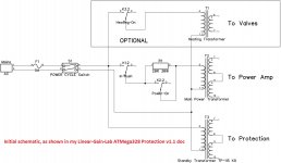
Here's a schematic I drew up for another member here to explain how to wire a monoblock subwoofer amp. It shows the proper connection for the power/inrush relays. When time permits, I will draw a better one with all options for the control board.
Attachments
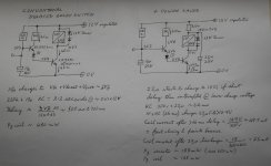
standard relay driver switch
and power saver version.
The coil switch must run saturated
That requires the first transistor to pass approx 10% of coil current.
A high gain first transistor reduces the risk of the timing capacitor not charging fully, or as fast as the RC value would predict.
The switching transistor can be any with a current rating approximately double the peak coil current.
Even an ungraded BC546/547/549/550 would do. any 600mA cheap transistor will also do.
Reform the timing capacitor before assembly or use a film type.
330k and <=3u3F work well. Much higher than 360k will need a high gain first transistor.
If a mosFET is used as the switch, the LED for increased triggering voltage will not work. You would need an extra gate to source resistor to pull current through the LED.
Attachments
Last edited:
Thanks Andrew. This looks like a good option in an analog design. I'm switching the relays through a ULN2003 Darlington transistor array, so this would add a lot of extra circuitry to mine.
I've thought of an easier way to accomplish the same thing with digital controls. I've been thinking of controlling/monitoring everything over I2C to remove more wire from the amplifier. An easy way would be to activate a spare output on an I2C expander to ground the relay through a resistor after pull in.
I've thought of an easier way to accomplish the same thing with digital controls. I've been thinking of controlling/monitoring everything over I2C to remove more wire from the amplifier. An easy way would be to activate a spare output on an I2C expander to ground the relay through a resistor after pull in.
darlington relay drivers are NOT good switches.
They drop Vce sat of ~ 0.8V to 1.0V
A saturated singleton transistor driver drops <0.1Vce.
5V relays would not switch as effectively. Not so much of a problem for 12V relays and problem goes away with 24V relays.
I would always adopt as high a voltage relay as I have in stock, or the circuit would allow if I have to buy a special.
The relay is switched, by a transistor.
All that changes is the the relay is fed form a higher voltage via a dropping resistor and a cap to kick the relay ON.
That can be applied to a darlington itself driven from a 5V control circuit.
Last edited:
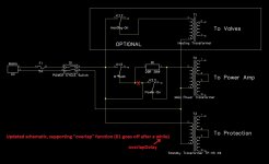
Guys, just a clarification for those who is using "Linear-Gain-Lab ATMega328 Protection v1.1" doc as a guide - attached are the initial power relays wiring (white) and the updated one (black).
Here is an additional parameter in the firmware v06 - overlapDelay:
const int TubesAreHere = 0;// 1 = Tubes, 0 = NO Tubes
long heatingDelay = 25000; // wait for tubes pre-heat, if tubes are here (mS)
long inrushDelay = 2000; // wait for soft start (mS)
long overlapDelay = 500; // overlap before inrush goes off, if "0" - stays on (ms)
long speakersDelay = 4500; // wait before connecting speakers (mS)
Cheers,
Valery
P.S. Let me know if you need v06 firmware.
Attachments
Last edited:
A relay driver ouput pin drops the same voltage as a single pn junction (.6V) . It houses the protection diode as well in a neat little package.
http://www.onsemi.com/pub_link/Collateral/ULN2003A-D.PDF
I work in the automotive industry, so 12V relays are always on hand, so this works best for me.
http://www.onsemi.com/pub_link/Collateral/ULN2003A-D.PDF
I work in the automotive industry, so 12V relays are always on hand, so this works best for me.
Last edited:
No.
Vbe unsaturated is ~0.6V and Vce unsaturated can be anywhere from 0.2V to 100V
But when saturated the numbers change.
Vbe saturated is ~ 0.8V and Vce saturated ~ 0.05V
And a darlington is different again,
Vbe sat ~ 1.4V and Vce sat ~0.8V (edit changed this to Vce sat ~ 0.9V)
The ONsemi datasheet confirms.
Vce sat varies from a stated low of 0.85V, to a high of 1.6V
Last edited:
I lost the ball completely....
So many versions,different pcb all in the same thread
I will publish an updated v1.2 document in the first post soon, describing the current finished, "production" version 😉
I have a quick Arduino code class question. Should these longs be unsigned? What happens when millis rolls over to a negative value?Guys, just a clarification for those who is using "Linear-Gain-Lab ATMega328 Protection v1.1" doc as a guide - attached are the initial power relays wiring (white) and the updated one (black).
Here is an additional parameter in the firmware v06 - overlapDelay:
const int TubesAreHere = 0;// 1 = Tubes, 0 = NO Tubes
long heatingDelay = 25000; // wait for tubes pre-heat, if tubes are here (mS)
long inrushDelay = 2000; // wait for soft start (mS)
long overlapDelay = 500; // overlap before inrush goes off, if "0" - stays on (ms)
long speakersDelay = 4500; // wait before connecting speakers (mS)
Cheers,
Valery
P.S. Let me know if you need v06 firmware.
Post1 allows updates and indexes and other useful links to be added by the Thread opener at any time.I lost the ball completely....
So many versions,different pcb all in the same thread
There is no need for getting lost. The Thread opener can keep everyone up to date if he/she cares to take the time.
More than a year since the opener/Designer showed us his creation, yet there is no mention of an edit.
Last edited:
Post1 allows updates and indexes and other useful links to be added by the Thread openier at any time.
There is no need for getting lost. The Thread opener can keep everyone up to date if he/she cares to take the time.
Yes, that's what I mean... I just did not really take the time yet, but I will do so tomorrow 😀
No.
Vbe unsaturated is ~0.6V and Vce unsaturated can be anywhere from 0.2V to 100V
But when saturated the numbers change.
Vbe saturated is ~ 0.8V and Vce saturated ~ 0.05V
And a darlington is different again,
Vbe sat ~ 0.9V and Vce sat ~0.8V
The ONsemi datasheet confirms.
Vce sat varies from a stated low of 0.85V, to a high of 1.6V
Does not make any practical difference in our particular case, right?
The relay goes on and off reliably anyway.
No.
Vbe unsaturated is ~0.6V and Vce unsaturated can be anywhere from 0.2V to 100V
But when saturated the numbers change.
Vbe saturated is ~ 0.8V and Vce saturated ~ 0.05V
And a darlington is different again,
Vbe sat ~ 0.9V and Vce sat ~0.8V
The ONsemi datasheet confirms.
Vce sat varies from a stated low of 0.85V, to a high of 1.6V
Measurements with my voltmeter show otherwise. I measure .6V whenever I test. Actual pull in voltage of a t90 relay is 9V so really even a 1.6V drop wouldn't be a concern.
Thank you. That really helps when there are changes that need to be tracked.Yes, that's what I mean... I just did not really take the time yet, but I will do so tomorrow 😀
- Home
- Amplifiers
- Solid State
- How to build a 21st century protection board