That is great Terry, may i have the gerbers?.
Quan
Hopefully I did this right. I couldn't get it to export the outline. Try sending it to the board house and see.
Attachments
Hopefully I did this right. I couldn't get it to export the outline. Try sending it to the board house and see.
Thanks Terry.
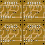
The board or 48mm x 48.5mm.
we could fit 4 of them on one 10cm x 10cm board and get in under the prototype discount. I'm not sure what they charge for score lines but that would be a really cheap way to do it. I was able to put 6 of them on a 4" X 6" board. These should work well in a tight chassis when using a reasonable sized PSU.
Terry, this is fantastic!

Hey Terry,
I looked at your fab data, looks okay to fab with. I did notice that the data is in the -ve offset/co-ordinate from a (0,0) datum, but i do not think that will matter.
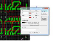
i see a bunch of small dots in the silk, look to small to do anything of use.
Suggestions, for future pcbs
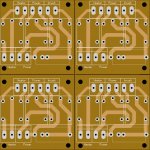
1) since 2 sided fab is the same $ as one sided(on pcbway for example), make use of the top layer and double up on the traces. Gives you a plated TH barrel, for more strength and more current capacity with the extra copper.
2) add the board outline(s) in the silkscreen layer.
For scoring you can do a few tricks
1) could use a whole bunch of holes spaced close together along the break line.
2) Provide milling data to mill out most of the images and have a few small holes to keep the images together. This depends on the cad tools capabilities to panelize images.
Good luck
I looked at your fab data, looks okay to fab with. I did notice that the data is in the -ve offset/co-ordinate from a (0,0) datum, but i do not think that will matter.
i see a bunch of small dots in the silk, look to small to do anything of use.
Suggestions, for future pcbs
1) since 2 sided fab is the same $ as one sided(on pcbway for example), make use of the top layer and double up on the traces. Gives you a plated TH barrel, for more strength and more current capacity with the extra copper.
2) add the board outline(s) in the silkscreen layer.
For scoring you can do a few tricks
1) could use a whole bunch of holes spaced close together along the break line.
2) Provide milling data to mill out most of the images and have a few small holes to keep the images together. This depends on the cad tools capabilities to panelize images.
Good luck
Last edited:
Thanks for the tips. Sprint adds those little dots. I'm not sure why. Maybe Jeff can tell me how to eliminate them. I like the idea of the little holes to create score lines. Easy enough to double the foil on top and make the pads through hole. On my first layout the pads were through hole. For some reason I thought it was cheaper to get single sided. Maybe that is only for boards that are over 10cm. I will change these to two sided and create new gerbers.
Good to hear my advise is of use.
They usually run 18x24" production panels, that puts a lot of 100x100mm images on one panel 🙂
With this cheap process, all you will get is PTHs even if it a 1 sided image. Adding npths is another process step (done after etching) and another drill file. You can not mix pth and npth holes in the same excellon drill file, they have no way to differentiate one drill hit from another.
Terry can you post or send me gerbers or pdf from this arduino nano based protection board?Here are the two boards together.
Good to hear my advise is of use.
They usually run 18x24" production panels, that puts a lot of 100x100mm images on one panel 🙂
With this cheap process, all you will get is PTHs even if it a 1 sided image. Adding npths is another process step (done after etching) and another drill file. You can not mix pth and npth holes in the same excellon drill file, they have no way to differentiate one drill hit from another.
They can figure out if the hole is through plated if it has pads around the hole. I only send one drill file and have never had an issue.
Terry,The board or 48mm x 48.5mm.
we could fit 4 of them on one 10cm x 10cm board and get in under the prototype discount. I'm not sure what they charge for score lines but that would be a really cheap way to do it. I was able to put 6 of them on a 4" X 6" board. These should work well in a tight chassis when using a reasonable sized PSU.
Have you tested these boards yet. The reason I ask is cause my relays have a different Pin out.
Attachments


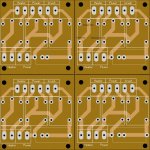
Can I ask if this is the correct Truth table for the SoftStart Relays boards?
The softstart line should't be there. Softstart = Inrush. The Inrush relay turns on, pause for the delay time, the power relay turns on, then the inrush relay turns off after the overlap delay.
I think I have this correct ( see top right board in the picture). Relay datasheets are never really clear. The safest way to connect mains power when you are only using the NO contacts is to bring power in through the NO contact, and out through the Common pin. This way you will have less live pins to have a chance of coming in contact with. Another thing I try to do, and it looks like you have done, is keep topside mains power traces under components. You have them well covered by the relays.😎
Attachments
Last edited:
The softstart line should't be there. Softstart = Inrush. The Inrush relay turns on, pause for the delay time, the power relay turns on, then the inrush relay turns off after the overlap delay.
Kool. Inrush is signal name. SoftStart is a state not a signal.
Thanks.
Sent from my HUAWEI MT7-L09 using Tapatalk
The "inrush" circuit switches on first to feed the mains voltage (120Vac) through a resistor to ease the inrush of current into to the filter caps. After about three seconds the "power" circuit switches on to bypass the resistor. After that the "Inrush" circuit switches off to relieve the inrush relay draw from the 12Vac transformer.
- Home
- Amplifiers
- Solid State
- How to build a 21st century protection board