Coming Along
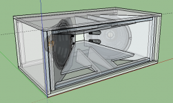
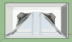
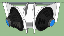
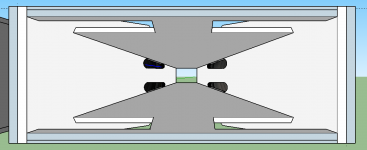
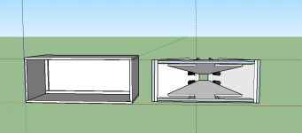
Some correction made to the model, which appears to be measuring up and squaring up just right.
Some correction made to the model, which appears to be measuring up and squaring up just right.
Attachments
-
 Screen Shot 2015-11-11 at 2.40.08 pm.png84.6 KB · Views: 1,811
 -
 Screen Shot 2015-11-11 at 2.37.12 pm.png90.3 KB · Views: 1,783
 -
 Screen Shot 2015-11-11 at 2.34.22 pm.png27.2 KB · Views: 1,738
 -
 Screen Shot 2015-11-11 at 2.32.48 pm.png58.7 KB · Views: 1,728
 -
 Screen Shot 2015-11-11 at 2.51.37 pm.png276.7 KB · Views: 998
 -
 Screen Shot 2015-11-11 at 2.52.29 pm.png61.7 KB · Views: 1,027
 -
 Screen Shot 2015-11-11 at 2.53.47 pm.png114.6 KB · Views: 994
 -
 Screen Shot 2015-11-11 at 2.55.04 pm.png93.9 KB · Views: 1,744
Last edited:

I have messaged Art asking permission to publish the model.
I'm using sketchup because it is quick and easy.
Once the dimensions are verified we will import it into solidworks and create cut plans.
I need to clear up the port locations though, they don't look right.
I'm using sketchup because it is quick and easy.
Once the dimensions are verified we will import it into solidworks and create cut plans.
I need to clear up the port locations though, they don't look right.
Just because I havent bothered to learn to drive it yet.
Will transport to SW shortly.
Will transport to SW shortly.
Last edited:
I have messaged Art asking permission to publish the model.
Cool, I'm excited to open it in Sketchup and just 'look around'.
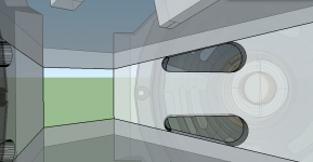
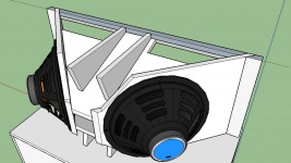
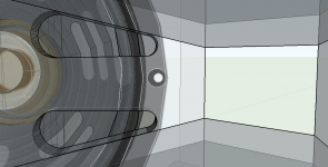
Fin,Corrected the positioning of the injection ports.
The port position now appears right, but is lacking the details of the throat chamber, which would be visible as a thicker depth at the mouth end of the port, and less than 1/2" depth at the throat end.
Art
Attachments
Acknowledged Art!
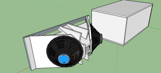
I am yet to model the CD mount piece and the Front Horn.
ALL: Art as given the OK to publish the model. I want to put it somewhere where anyone can DL it. Let me look around for a repository.
(it doesnt seem to like living on github!)
I am yet to model the CD mount piece and the Front Horn.
ALL: Art as given the OK to publish the model. I want to put it somewhere where anyone can DL it. Let me look around for a repository.
(it doesnt seem to like living on github!)
If the model is under 1.82MB you can rename it to a .asc extension and upload it to this thread.
My idea was one link that gets the latest file.
That way there isnt a truck load of models stuck to the forum.
That way there isnt a truck load of models stuck to the forum.
OK here is a link to the model as it currently stands.
https://drive.google.com/file/d/0BwGf5Kb0D758Skl4Sk02a2Zaenc/view
You will need to download sketchup version 15.
Download SketchUp | SketchUp
https://drive.google.com/file/d/0BwGf5Kb0D758Skl4Sk02a2Zaenc/view
You will need to download sketchup version 15.
Download SketchUp | SketchUp
Last edited:
If anyone would like to confirm the current measurements in the model that would be great!
otheriwse, I think its time to get cutting.
I am going to do a build out of 1/2" mdf first, to make some inexpensive templates and keep the cost of mistakes low.
Then I will make a second build out of good solid void free Marine Ply.
otheriwse, I think its time to get cutting.
I am going to do a build out of 1/2" mdf first, to make some inexpensive templates and keep the cost of mistakes low.
Then I will make a second build out of good solid void free Marine Ply.
Fin,If anyone would like to confirm the current measurements in the model that would be great!
I don't see any measurements in the model.
Attachments
Hi Art!
No not yet. I was going to put them in the cut sheet model.
What can be done with sketchup is use the MEASURING TOOL that looks like a measuring tape, and make some measurements.
And also use the PROTRACTOR tool to measure angles.
I am currently looking at the plug for the 10" drivers and working out how to manufacture them. Maybe a pivot and a router mounted on an angle.
210 CC's was the last noted measurement in the other thread.
Also I am looking for a reference point to mount the 10" driver.
Was there a reference point noted anywhere?
Was there a reference point noted anywhere?
Fin,Also I am looking for a reference point to mount the 10" driver.
Was there a reference point noted anywhere?
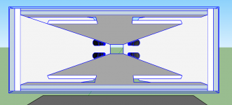
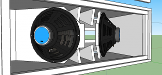
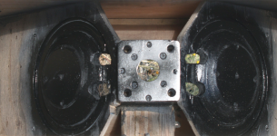
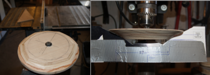
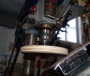
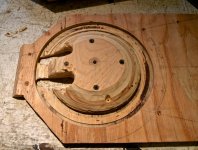
Unfortunately not. The back of 10" mounting ring is almost touching the driver plate (as can be seen in the plans in post #41) from the photo below you can see the location.
I used a drill press and belt sander to shape the filler cone profile (made from a 3/4" circle cutout), comparing it to a paper template of the cone profile. The first one took a long time, then I realized about 75% of the material that needed to be removed could be cut off with the table saw, minimizing the sanding.
Art
Attachments
Hi Art,
What influence would you consider the ports/their positions to have in regards of the cabinets spatial identity within a room/area if set up correctly as a stereo pair?
Will this make the cabinets positions in the room more pronounced hence reducing 3d/stereo image compared to if all the sound were radiating from the horn apex as if it was not ported?
- Home
- Loudspeakers
- Multi-Way
- SynTripP: 2-way 2-part Virtual Single Point Source Horn