They are cathode biased, so you subtract the cathode voltage to determine the actual voltage across the tube.
Plate voltage is not what kills tubes - it's power dissipation. A small plate overvoltage won't hurt the 5842's.
Win W5JAG
Plate voltage is not what kills tubes - it's power dissipation. A small plate overvoltage won't hurt the 5842's.
Win W5JAG
The rule of thumb I use for "hot" is that you should be able to hold your finger on the heatsink. If you touch it and immediately pull away due to pain it is too hot. If you can put your finger on it for several seconds you are probably fine.
Elliot has a good write-up on proper heatsinking here: ESP - Heatsink design and transistor mounting
A lot of these devices are designed to run hot, that is just how they work. Without a true temperature reading, I would not be too concerned with perception of hot by simply touching them and assuming there is a problem. If the math calculation is less than the power rating, the device will be fine. Just make sure those resistors are spaced off the PCB and not touching anything else.
Thanks for the tips evanc, Win, and craigtone. I'll study the math and theory of heatsinking before dealing with that.
I swapped in a 7k 10w resistor at R7 and retook the measurements.
B- is now about -148V
I also measured the grid voltage of the 300Bs (across pins 1&3) at just under -70v when the bias was set to just under 77mA. -70v would seem to be too much for the Vgs (30v) of my MOSFETs, no? Perhaps that's what's contributing to all the heat?
Here is the series of tests (using shorting plugs at the RCA input jacks and 8 ohm dummy loads at the speaker terminals), including temps at the bottom.
No tubes
• B+ = -27
• B- = -148
• Filament voltage (pins 1 & 4) = 4.93
• Filament current (pins 1 & 4) = 4.95
With rectifier
• B+ = 478
• B- = -147
Output tube grid voltage set to most negative (with rectifier, without 300Bs)
• B+ = 482
• B- = -152
• L grid (pin 3 to ground) = -80
• R grid (pin 3 to ground) = -80
With 5842s
• B+ = 462
• B- = -151
• L plate (C11 to ground; tip jacks) = 154.4 (set to match right channel)
• R plate (C9 to ground; tip jacks) = 154.4 V (highest it could go)
With 300Bs, bias and voltage
• B+ = 372 → 368 (over 20 minutes)
• B- = -148 → -146 (over 20 minutes)
• L bias (300B) = 76.9mA (across R29); -69.6v (across pins 1 & 3)
• R bias (300B) = 76.7mA (across R18); -69.5v (across pins 1 & 3)
• L plate (5842) = 160.7 V; 9.7mA (C11 to ground; tip jacks)
• R plate (5842) = 160.7 V; 9.7mA (C9 to ground; tip jacks)
• C4 voltage (positive lead to ground) = 406
• C5 voltage (positive lead to ground) = 371
• C6 voltage (negative lead to ground) = -411
• C7 voltage (negative lead to ground) = -146
• D2 voltage (close lead of R5 to ground) = -418
• Voltage drop across R6 = 263
• Voltage drop across R7 = -147
Temperatures (in *F)
• R6 = 208
• R7 = 146
• R4 = slightly warm to touch
• R14 & R25 = 96; 108
• U1 (filament voltage regulator) = 145
• U2 & U3 (10M45 CCS chips) = 173; 180
• Q1 & Q2 (MOSFETs) = 137; 152
• D1 (dual Schottkey rectifier) = 143
• D2 or D3 (whichever remains) (Hex FRED) = room temp
• D4 & D5 (1N5401 diodes) = 115
• PT – slightly warm to touch
• OPTs – cool to touch
Last edited:
Since the grid voltage of the 300b is supposed to be -60v, I tested the range with the 7k at R7, and managed to get these before rushing to get my kid at school.
B+ 380
Grid -85v
Bias 64 mA
B+ 374
Grid -75v
Bias 73.5 mA
B+ 361
Grid -62.5v
Bias 85.3 mA
B+ 355
Grid -59v
Bias 89 mA
I was going for a bias of around 90mA, so that setting seems to be right in the sweet spot of the tube.
I was curious to know what the 5842s were doing, so I took another measurement with a more accurate multimeter.
B+ 356v
Grid -61.7v
Bias 90mA
5842 Plate voltage 160v
5842 Plate current 9.8mA
Per the engineer's suggestion, I'm going to purchase a 6.8k 25w chassis mount resistor for R7 and a 10k 25w chassis mount for R6, as well as a pair of this MOSFET with a higher Vgs to handle the 300B grid voltage:
STW20N65M5 STMicroelectronics | Mouser
That B+ of 356 looks low (measured across R30), but everything else seems to check out.
a bit off the reservation
Hello,
I am reading with great interest the trials of jdrouin and craigtone. I have my own trials that are a bit off the reservation. Perhaps someone can see what I cannot...
My very first set of readings (no tubes in place) is not like jdrouin's at all: B+ =+270VDC, B- = -375VDC, and across the heater pins of the output 300B tube sockets: -1.8VDC. The only thing that is about right is the 6.2VAC I have at T1-8 and T1-7 😱
off reservation cont.
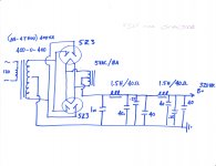
The B+ comes into the TSE board at the positive terminal of where C5 would go.
The B- is developed from voltage taken at the plates of the 5Z3s down to T1-4 and T1-5. T1-1 is brought to signal ground as is the "lower ground" from my PSUII drawing. And signal ground gets back to chassis ground through double diodes.
The (fairly) accurate 6.2VAC goes in at T1-8 and T1-7.
I guess it is not surprise that the B- is so high as it is developed from 400VAC. I don't know how to tame that. Maybe a big increase in R7?
The surprise to me is 270VAC positive B+ where a negative was expected and a -1.8VDC on the heater sockets.
What oh what have I done?
Attachments
more data off the rez
I should also describe where I am at in the process. I'm just at paragraph 3.
I might say again it is acrosss the socket points for the heaters of the 300B that I get the silly -1.8VDC
And mention that the heat sink for U1 got pretty hot.
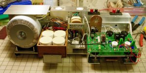
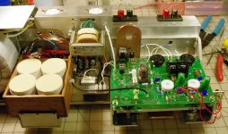
This is the really strange thing to me; the 6.3VAC is correct, the parts were all checked against the BOM, the sockets were kind of a mystery though because the lettering/pin numbering on the board did not match the schematic and I decided to match the schematic. If you look at my photos, the larger pin sockets are on the right hand side for each placement...
Did everyone else do it this way??
I should also describe where I am at in the process. I'm just at paragraph 3.
I might say again it is acrosss the socket points for the heaters of the 300B that I get the silly -1.8VDC
And mention that the heat sink for U1 got pretty hot.
This is the really strange thing to me; the 6.3VAC is correct, the parts were all checked against the BOM, the sockets were kind of a mystery though because the lettering/pin numbering on the board did not match the schematic and I decided to match the schematic. If you look at my photos, the larger pin sockets are on the right hand side for each placement...
Did everyone else do it this way??
Attachments
Hi jdg123,
I have found that for my 300B build, some of the parts in the BOM do not work. I think a lot of those parts and their values are geared toward a 45 or 2A3 build. It was a local engineer who helped me figure that out. I'm a complete novice and don't always know what questions to ask, though I've learned a *LOT* in the past couple weeks.
Electricity is a very strange thing.
Your 300B sockets are installed correctly.
With no tubes in, if you measure across pins 1 & 4 (the big ones) with a multimeter you should have 5V DC. Make sure your meter is set to DC.
If not, then there might be something wrong with the voltage regulator, or between the regulator and the 300B sockets.
Did you test for connectivity and resistance values from point to point in the schematic? All capacitors oriented correctly? You might find a bad connection, incorrect value, or misfunctioning part somewhere.
Also, check the wiring of your PT to the board, because there might be something amiss there.
You're going to need a *big* heat sink for the U1/D1 assembly. I've been reading through this page and finding it very helpful for understanding thermal transfer and resistance in heatsinks: http://sound.westhost.com/heatsinks.htm#s15.
One thing I didn't know before is that the grid voltage of the 300Bs has to be handled by the MOSFETs. The grid voltage of a 300B, according to the datasheet, is about -60VDC, so your MOSFETs need a gate voltage (Vgs) of at least that amount. The Toshiba 2SK3565 that I installed have a Vgs of only 30V, so I ordered ones with a Vgs of 130V (http://www.mouser.com/ProductDetail/STMicroelectronics/STW20N65M5/?qs=sGAEpiMZZMshyDBzk1%2fWi%252bxYNiIMxqHxPO8qojwq1Ho%3d).
I hope that helps.
Jeff
Last edited:
Maybe this will make you fellas feel better ... ( or not ) ....
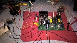
Here is a TSE powered up with flying leads everywhere, after a five or six year hibernation ....
45, biased to 27 mils, didn't check any other voltages. Wife and baby are out of town, so I was going to start working on changing it to run 801's .... until I checked the regulator spec and realized it has a max voltage of 5 volts, so I'm going to have to back up and ponder that a while longer. I wound up just listening to it through the working channel for an hour or two.
Strictly for what it's worth, I think I might consider getting the board working with the parts Tubelab spec'ed and as Tubelab designed it, and make sure it's working the way it was intended to work, before I started changing parts, modifying things, and adding external power supplies, etc. It just seems like modifying it before it is ever known to be working properly is asking for problems, and potentially adding a lot of extra troubleshooting headaches. How do you know if the problem is in the basic build, or the mods, otherwise?
Other than some fussing over the FET's to use, and heatsinking, I don't recall there being any problems with the amp, with 45/2A3 or 300B's. Again, strictly for what its worth.
Win W5JAG
Attachments
Last edited:
Thanks!
Hey guys thanks,
jdrouin, I checked out the MOSFET you had a link for: STW20N65M5 but the data sheet shows a Vgs of +/-25V. Maybe the link is wrong? I used IRF830APBF because I read through the thread about how the original MOSFET was inobtanium and that IRF part was recommended. We are all slightly adrift building this design now.
Your warning about the heat sink is noted! I have a copper plate for mine but I might add more to it. One thing I did not note as a varriance is that though the diode is properly isolated from that heat sink, the voltage regulator is not isolated (as per directions) and that heat sink (my copper heat sink) is by its construction grounded where I think the original is not. This may be the whole problem??!!??
W5jag, you are good to point out I am way off the reservation here. It seemed like a good idea at the time... Geo has built 300Bs before on this board and though he does it using the board as intended he has skipped parts of the board in some other applications like the 845 build. Now he does this with a complete knowledge of the whole design, something I am not at all possesed of. I was walking on the wild side to try to bring in my own PSU but everything else was by the book. I just figured I'd leave out everything from the tube diode plates on and pick it back up at the final cap out...put in my own stuff which should have been fine and right but there is something wrong in my assumption. I have overlooked something basic. I must find it. I must learn😀
I would very much appreciate a second set of eyes though. It is dang tough to be your own editor
I've been reading about the operation and characteristics of MOSFETs because I realize they're deceptively complex and I really didn't understand what I was doing. I'll have more to say about that in post soon. I think what I'm starting to grasp is that the MOSFET in each channel of the TSE functions like an analog switch that flows both ways, with the source being on the most negative side (the 300B grid voltage plus the bias supply) and drains on the more positive side (i.e. for the right channel, the chain of R18/OPT/300B anode). It might be the gate-source breakdown voltage -- V(br)gss, the total voltage handling across the source and drain pins -- that matters in my applications. So it's not just the gate-source voltage (Vgs) but the value across the whole FET that matters. The Toshiba 2SK3565 has a V(bd)gss of 30v, whereas the STM's is 650v.
Here's a comparison table I made at Mouser. Left to right: Toshiba 2SK3565, STMicroelectronics STW20N65M5, Fairchild FDPF5N0NZ, Toshiba 2SK2700 (now obsolete, in George's original design). I'm still thinking through this but wanted to post the info up here incase anyone else wants in the process (lucky you!).

In the meantime, my MOSFETs arrived and I ordered the wrong format (TO-247-3 instead of TO-220) because I wasn't paying attention. So I'll either mount these off-board with larger heatsinks or order the TO-220s.
Here's a comparison table I made at Mouser. Left to right: Toshiba 2SK3565, STMicroelectronics STW20N65M5, Fairchild FDPF5N0NZ, Toshiba 2SK2700 (now obsolete, in George's original design). I'm still thinking through this but wanted to post the info up here incase anyone else wants in the process (lucky you!).
In the meantime, my MOSFETs arrived and I ordered the wrong format (TO-247-3 instead of TO-220) because I wasn't paying attention. So I'll either mount these off-board with larger heatsinks or order the TO-220s.
Also check out the TK5A50D which is the Toshiba recommended substitute for the 2SK3563 that George designed the amp for.
I saw the TK5A50D when I was sourcing parts originally but forget why I didn't buy it. No good reason, apparently.
I'm starting to think about mounting these new MOSFETs off-board so that I have room to heatsink them and the 10M45s properly. Do you think mounting the MOSFETs off-board would hamper performance/sound?
Here they are with my new R6 and R7. Things are getting serious... ;-)
 Untitled by jeffdrouin, on Flickr
I'm starting to think about mounting these new MOSFETs off-board so that I have room to heatsink them and the 10M45s properly. Do you think mounting the MOSFETs off-board would hamper performance/sound?
Here they are with my new R6 and R7. Things are getting serious... ;-)
Untitled by jeffdrouin, on Flickr
Last edited:
Jeff,
Another possible option? NTE 2903 Mosfet from MCM Electronics:
NTE Electronics Mosfet N-channel Switch | NTE2903 | NTE Electronics
Another possible option? NTE 2903 Mosfet from MCM Electronics:
NTE Electronics Mosfet N-channel Switch | NTE2903 | NTE Electronics
Jeff,
Another possible option? NTE 2903 Mosfet from MCM Electronics:
NTE Electronics Mosfet N-channel Switch | NTE2903 | NTE Electronics
Spec-wise that is almost identical to the 2SK3563! Nice find!
2sk3565 is available. I know this part works. My TSE with 45 tubes has been in daily use at my shop for quite some time.
2SK3565(Q,M) Toshiba Semiconductor and Storage | 2SK3565QM-ND | DigiKey
I did add a bit of extra heatsink but nothing extreme.
2SK3565(Q,M) Toshiba Semiconductor and Storage | 2SK3565QM-ND | DigiKey
I did add a bit of extra heatsink but nothing extreme.
Thanks for these suggestions. I'm using the 2SK3565 now, which according to the engineer I'm working with is not suited to the grid voltage of the 300b, though clearly it's fine for a 45 application.
I'm thinking of mounting my new MOSFETs off board. Is that a bad idea? Will it affect stability or sound?
Figured I'd put them in nice meaty heatsinks like this one:
R2A-CT4-38E Ohmite | Mouser
I'm thinking of mounting my new MOSFETs off board. Is that a bad idea? Will it affect stability or sound?
Figured I'd put them in nice meaty heatsinks like this one:
R2A-CT4-38E Ohmite | Mouser
Why not just keep the 2SK3565 and see if it's satisfactory in service?
When I popped my first ( and only ) FET, all it did was apply a bunch of negative bias to the 45, and cut it off. No damage was done. I replaced both with 2SK3563 and it's been fine since, for 45, 46, 47, 2A3 and 5930. You have no real assurance that anything else you might substitute will be a better solution. If you're worried about tube damage, you could get some cheap Sovteks as testers.
I'm hard pressed to see how you have anything to lose with that approach, and might save yourself some trouble. Anytime you go outside what the designer intended, you run the risk of adverse consequences. When you move the FET's, or any other part, off the board, you run the risk of wiring errors, and noise pickup on the leads. I suppose oscillation could also be a possibility.
When a solution to a (perceived ) problem, presents a number of potential additional problems, it may not be the best solution to the problem.
When you have an engineer effectively re designing something that is not generally accepted to be flawed, I can't help but wonder if this train is starting to leave the tracks.
My two cents, FWIW.
Win W5JAG
edit: the only thing that jumped out at me about 2SK3565 is the on resistance: 2 ohms. Less is better.
Last edited:
Spec-wise that is almost identical to the 2SK3563! Nice find!
Good find, indeed. I have a spare set of 2SK3563, but I might go by the local TV shop and see if they have a few of these in stock.
Win W5JAG
- Home
- More Vendors...
- Tubelab
- Tubelab SE 300b Build Thread