I've got Gerbers with corrections made to the silkscreen for those reversed capacitors.
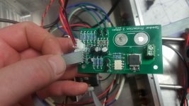
I'm also 3/4 done debugging the latest version with Mosfet relays at the speaker binding posts. It's an easier set of boards to assemble using standard through hole devices and has on board programming connections. I like this design better for installation. Much less wiring.
I'm also 3/4 done debugging the latest version with Mosfet relays at the speaker binding posts. It's an easier set of boards to assemble using standard through hole devices and has on board programming connections. I like this design better for installation. Much less wiring.
Attachments
Last edited:
Reverced diodes?I've got Gerbers with corrections made to the silkscreen for those reversed diodes.
I'm also 3/4 done debugging the latest version with Mosfet relays at the speaker binding posts. It's an easier set of boards to assemble using standard through hole devices and has on board programming connections. I like this design better for installation. Much less wiring.
I'm also 3/4 done debugging......waiting to see this🙂
Reverced diodes?
I'm also 3/4 done debugging......waiting to see this🙂
I meant capacitors.
I think the next upgrade should be isolating the DC detection from the control board completely. As is using this on monoblock amp designs will be connecting the grounds together. Powering the DC detection from rail voltage instead of the DC alarm wire should work, then connecting through an optoisolator.
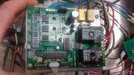
I've finally had some time to do some more in depth testing of my latest through hole designs. I've got a connector on board for programming via a FTDI USB to serial cable that I haven't managed to make communicate properly yet, but everything else seems to work well.
The remote speaker relays work well other than they seem to require a little higher voltage to activate than I would like. Positive voltage trips at 3V. Negative at -2.7V. When I used bridges it would trip closer to 2V. Short of lower forward voltage diodes, I haven't been able to figure out how to adjust the trip point. I'm not sure if it'e really worth worrying about either. 3V would be 2.25W on a 4 ohm speaker.
The remote speaker relays work well other than they seem to require a little higher voltage to activate than I would like. Positive voltage trips at 3V. Negative at -2.7V. When I used bridges it would trip closer to 2V. Short of lower forward voltage diodes, I haven't been able to figure out how to adjust the trip point. I'm not sure if it'e really worth worrying about either. 3V would be 2.25W on a 4 ohm speaker.
Attachments
I'm building Jeff's V3.2 board. Is there a diagram somewhere showing a "standard" wiring scheme? I am planning to use is for a hybrid so I will need the heater function but I'm not clear what other features I will need. I'm assuming I will need some additional relays but not sure what. I tried following the procedure that OS went through trying to get his working but I got lost when the conversation wandered into software issues and then the new boards came out and the whole thing changed gears.
Anyway, if someone created a diagram it would be helpful.
Thanks, Terry
Anyway, if someone created a diagram it would be helpful.
Thanks, Terry
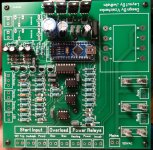
The top row of connections left to right are as follows.
LED + & - _ Front panel indicator LED
Tubes _ Tube heater transformer relay
Power _ Main power supply transformer relay
Inrush _ Main power transformer feed through a power resistor relay
D12 & D13 _ Extra unused outputs
Temperature _ These go to a MJE340 connected as a diode on each heat sink for temp sensing
Bias _ These connect to the transistor side of a pair of emitter resistors for overcurrent sensing
12V _ Remote starting from a 12V trigger signal
Audiolab _ Remote starting from Audiolab audio equipment
PWR _ To a toggle switch for manual start up.
12VAC _ From a 12V control transformer
Rails _ To the amplifier rail feed from the supply
The other two connectors are for speakers.
I've got a couple drawings somewhere. I'll upload them when I find them. This is the board that D4 (5.1V zener) is reversed in.
Attachments
Last edited:
Here's a grounding scheme that I drew up for another member. It shown how to connect the inrush resistor and power relays.
The power relays are any 12VDC coil high current relay. I used these T9AP5D52-12 TE Connectivity / P&B | Mouser They're cheap and very robust relays.
The power relays are any 12VDC coil high current relay. I used these T9AP5D52-12 TE Connectivity / P&B | Mouser They're cheap and very robust relays.
Attachments
Hi Jeff,The top row of connections left to right are as follows.
LED + & - _ Front panel indicator LED
Tubes _ Tube heater transformer relay
Power _ Main power supply transformer relay
Inrush _ Main power transformer feed through a power resistor relay
D12 & D13 _ Extra unused outputs
Temperature _ These go to a MJE340 connected as a diode on each heat sink for temp sensing
Bias _ These connect to the transistor side of a pair of emitter resistors for overcurrent sensing
12V _ Remote starting from a 12V trigger signal
Audiolab _ Remote starting from Audiolab audio equipment
PWR _ To a toggle switch for manual start up.
12VAC _ From a 12V control transformer
Rails _ To the amplifier rail feed from the supply
The other two connectors are for speakers.
I've got a couple drawings somewhere. I'll upload them when I find them. This is the board that D4 (5.1V zener) is reversed in.
That is a different board. Is there a write up for the V3.2 board as well?
Looks like I need external relays for inrush, power, and heater. I don't know what 12v trig or Audiolab are for.
One more thing, there is what looks like an smd pad next to U6. What is that for?
Thanks, Terry
Attachments
Last edited:
Are you building the board that takes a Nano? If so that SMD pad was a jumper to put 12V to U6. Blob solder over it. There's no documentation for this board. It's built off Valery's first schematic.
12V _ Remote starting from a 12V trigger signal
Audiolab _ Remote starting from Audiolab audio equipment
The external connections are the same on all these boards up until my latest.
12V _ Remote starting from a 12V trigger signal
Audiolab _ Remote starting from Audiolab audio equipment
The external connections are the same on all these boards up until my latest.
Hi Jeff,
Yeah still don't know what a 12V trigger is nor Audiolab so I guess I don't need to worry about that. Did I see somewhere that there was a revised nano sequence file?
Thanks, Terry
Yeah still don't know what a 12V trigger is nor Audiolab so I guess I don't need to worry about that. Did I see somewhere that there was a revised nano sequence file?
Thanks, Terry
There are three ways to start the control board. You can use a power switch, or one of two triggers. A lot of high end audio gear has a 12V trigger system. With that system there is two small wires running between all the equipment. The master unit will put out a 12V signal that will turn everything else on. Audiolab brand equipment has their own design that closes a set of contacts. You use one of the three options and leave the other two unhooked.
There was an updated file to turn the inrush relay off after the power relay turned on to lighten the load on the 12V regulator. I'll send you it later today.
There was an updated file to turn the inrush relay off after the power relay turned on to lighten the load on the 12V regulator. I'll send you it later today.
Hi Jeff,
Thanks for the file. I uploaded it. If there is no diagram of the hook up, then let me ask a few questions.
1. Can I assume that there are at least three additional relays needed aside from the two on board?
2. Does the on board 12V transformer power all 5 relays?
3. How do you hook up the inrush and power terminals?
4. Rail Sense is a direct feed from the output of the PSU?
5. Each thermo attaches to a MJE340 that has B-C shorted and mounted to main heatsink?
6. What happens if it senses too high heat?
7. The bias terminals have two poles. what do each side attach to?
8. If I am using just one power switch, how does it connect?
Thanks, Terry
1. Yes there are three separate relays needed
2. Yes the onboard 12V supply powers all relay coils. The LM7812 needs lots of heat sink.
3. The Grounding Schematic in post 908 shows how the main power relays are connected. You will need a large power resistor for the inrush circuit. I use a 20 ohm 50 watt chassis mount resistor for mine, but it's much larger than necessary.
4. Yes this connects directly to the rail supply.
5. Yes. One on each heat sink.
6. If temperature gets too high, it turns off the speakers and shuts the amp down
7. The + connection goes to an emitter of a positive rail output transistor. The - connection goes to an emitter of a negative rail transistor. This measures the voltage across a pair of emitter resistors and uses this to sense output current. If it goes too high, it shuts off the speakers, then shuts off the amplifier
8. If you are just using a power toggle switch. connect the switch terminals to the two "PWR" connections. This switch can be very light. It will only need to carry a few mA at 12V. The control board takes care of all the heavy switching loads.
Last edited:
To test the control board. Fire it up without the rail powers connected and no bias or temp connections. It should go through the whole startup sequence, then when it is about to turn on the speaker relays, it should shut everything down and blink the LED at high speed. It will stay like this until you remove power from the control transformer or hit the reset button on the Arduino.
Next hook the rails to it and start it up again. It should go through the start up sequence, then turn the speaker relays on. Apply some voltage to the speaker connector. At around 2-3V everything should shut down and the LED should blink quickly again.
Restart it again and apply voltage to the bias connections. At around 4V the bias circuit should cause a shutdown, but this time the LED will blink at a slower rate.
Temp circuit operation can be tested by shorting the temp + and - connections together. This will again cause a shutdown and blink the LED at a different rate.
Power loss detection can be tested by quickly unplugging the control transformer and re-powering it. This again should cause a shut down, and blink the led at a different rate again.
I should also mention this board does not like to be connected through a bulb limiter. If you are going to be using this for testing, power the inrush and power relays from a separate feed, not the onboard fuse. The bulb will flash on when the inrush relay first closes if you have a large power supply and will cause the board to keep restarting. I had a control transformer melt down on my first board. I think this repeated restarting may have caused it.
Hi Jeff,
Thanks for the detailed answer. This board doesn't have any +or- symbols. Is there a way to tell which is which without trying to follow all the traces? You can see the board in post #909. Can you please check to make sure I have the Elco caps correctly oriented?
Thanks, Terry
Thanks for the detailed answer. This board doesn't have any +or- symbols. Is there a way to tell which is which without trying to follow all the traces? You can see the board in post #909. Can you please check to make sure I have the Elco caps correctly oriented?
Thanks, Terry
The square pad is positive. That's the one towards the mains feed connector on each pair. The caps all look correct too.
Great! What about the Rail Sense, LED and Thermo? And do my caps look right?
Thanks, Terry
PS, May I assume the pads marked Rails and Aux are both 120vac?
Thanks, Terry
PS, May I assume the pads marked Rails and Aux are both 120vac?
All positive connector pads are square. The Thermo connector with the two square pads is the same as the other. The center pad of the rail sense is ground.
The two pin rails connector is meant to feed the power and inrush relay mains. This is the one I was recommending you don't use with a bulb tester. The Aux connector feeds the heater relay mains.
All the caps look correct. Again square pads positive in the supply section.
The two pin rails connector is meant to feed the power and inrush relay mains. This is the one I was recommending you don't use with a bulb tester. The Aux connector feeds the heater relay mains.
All the caps look correct. Again square pads positive in the supply section.
- Home
- Amplifiers
- Solid State
- How to build a 21st century protection board