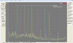
The CLD horn measurements posted above seem believeable to me. My MDF Edgar mid horns using the JBL LE-5 driver had 2nd harmonics ~-58dB with the higher orders getting a bit lost in the noise floor. I wish I'd measured a bit louder now to show up the higher orders better..😀
Attachments
I tend to use MDF as decent ply is very expensive here in the UK. I seem to recall a long time ago someone mentioned sandwiching 9mm MDF between 2 pieces of 6mm ply as a way of damping the resonances - the reason given was that when the ply wanted to resonate it was damped by the mdf and vice versa (due to differences in their resonant frequencies)
Does this theory have merit as it gives me an economical way of constructing better enclosures ?
Does this theory have merit as it gives me an economical way of constructing better enclosures ?
No. However a structure is constructed it will have a set of modes with associated resonant frequencies where the forces due to stiffness and mass cancel. At the resonant frequency it is only the force due to damping that will reduce the magnitude. Neither MDF or plywood has much damping and so you would need to generate damping via friction by sliding the sheets over each other. Not sure how much damping you would get but the structure is likely to be unacceptably weak. I seem to recall B&W or someone included something like this damping mechanism with their internal panel bracing.I tend to use MDF as decent ply is very expensive here in the UK. I seem to recall a long time ago someone mentioned sandwiching 9mm MDF between 2 pieces of 6mm ply as a way of damping the resonances - the reason given was that when the ply wanted to resonate it was damped by the mdf and vice versa (due to differences in their resonant frequencies)
Does this theory have merit as it gives me an economical way of constructing better enclosures ?
Something like 18mm plywood, 3mm rubber sheet, 6mm plywood on the other hand is likely to work very well with the right glue and the right rubber.
I tend to use MDF as decent ply is very expensive here in the UK. I seem to recall a long time ago someone mentioned sandwiching 9mm MDF between 2 pieces of 6mm ply as a way of damping the resonances - the reason given was that when the ply wanted to resonate it was damped by the mdf and vice versa (due to differences in their resonant frequencies)
Does this theory have merit as it gives me an economical way of constructing better enclosures ?
YES. It is certainly better than either material used on it's own. Can it be done even better? The answer is, YES, again.
This thread is another one of those never ending debates. Ask 25 different, experienced speaker enclosure builders, and you should get the same number
of correct, how-to-do it, answers.
Why? What is the physical mechanism that increases the damping?YES. It is certainly better than either material used on it's own.
Yep it's a wonder anybody actually gets to the 'building' stage considering the amount of theory needing to be waded through.. 😀
OSB is also cheap over here, maybe something decent could be done with that ?
OSB is also cheap over here, maybe something decent could be done with that ?
Something like 18mm plywood, 3mm rubber sheet, 6mm plywood on the other hand is likely to work very well with the right glue and the right rubber.
Hello Andy. Could you give an example of a set of right rubber and right glue for this?
FWIW, I'm thinking more about sealed enclosure construction (one for midbass, one for midrange) than horns.
Yep it's a wonder anybody actually gets to the 'building' stage considering the amount of theory needing to be waded through.. 😀
OSB is also cheap over here, maybe something decent could be done with that ?
Could be, but I am not experienced in the use of that material. MDF + ply works well because they are of dis-similar type. Their addition is greater than the sum of the parts. Rob, can you get hold of some 30# roofing felt ? If so, use it between the MDF + ply and you will have a nice sandwich. There are plenty more ways to construct a nice enclosure. Do a search for Von Schweikert speaker design theory for some interesting reading.
von-schweikert-audio
In that case go for 25mm MDF or 18mm plywood. It is only when you want higher performance you need to find out about how things work in order to make improvements.Yep it's a wonder anybody actually gets to the 'building' stage considering the amount of theory needing to be waded through.. 😀
In that case go for 25mm MDF or 18mm plywood. It is only when you want higher performance you need to find out about how things work in order to make improvements.
I've built plenty of enclosures from mdf, and a fair number from ply (back when I was working in a place that provided ply offcuts for free)
Now I have to buy my ply like everyone else so cost has become a factor, hence asking about alternatives.
I tend to use MDF as decent ply is very expensive here in the UK. I seem to recall a long time ago someone mentioned sandwiching 9mm MDF between 2 pieces of 6mm ply as a way of damping the resonances - the reason given was that when the ply wanted to resonate it was damped by the mdf and vice versa (due to differences in their resonant frequencies)
Does this theory have merit as it gives me an economical way of constructing better enclosures ?
Check out what Ztransform did with two layers of MDF and rubber sandwich. He used garden pond liner material.
http://www.diyaudio.com/forums/multi-way/252593-novel-open-baffle-construction-techniques.html
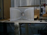
Thanks for the data on the Edgar tractrix. That was the horn that inspired me to make my foam core tractrix horns. Doesn't seem so crazy to get low HD given use of state of art drivers with modern Nd motors.
"Deflection" may be the key word on this thread, as it pertains to flexibility of wood, its byproducts or imitators, when the goal seems to be having Zero flex, as would be the case with thick maple butcher block.
This may be handy
http://www.woodbin.com/calcs/sagulator/
via Tapatalk
This may be handy
http://www.woodbin.com/calcs/sagulator/
via Tapatalk
Rob, can you get hold of some 30# roofing felt ? If so, use it between the MDF + ply and you will have a nice sandwich. There are plenty more ways to construct a nice enclosure. Do a search for Von Schweikert speaker design theory for some interesting reading.
von-schweikert-audio
Yep roofing felt is available here, will have a read up,
Thanks Scott.
Check out what Ztransform did with two layers of MDF and rubber sandwich. He used garden pond liner material.
http://www.diyaudio.com/forums/multi-way/252593-novel-open-baffle-construction-techniques.html
Thanks for the data on the Edgar tractrix. That was the horn that inspired me to make my foam core tractrix horns. Doesn't seem so crazy to get low HD given use of state of art drivers with modern Nd motors.
Feed Tubs like this have a thick, dead rubber which apparently goats can't chew. I saw and handled one at a Walmart & was impressed by its durability and lack of resonance.
http://www.amazon.com/Miller-Manufacturing-HP8-Rubber-8-Quart/dp/B000BD8JYK
via Tapatalk
Given how well latex caulking between two layers of foam core worked I would almost bet it would work for MDF sandwich. It is very quick and easy to apply post-facto. That is, you don't have to make the whole structure out of CLD. Build as normal then add a thick layer of latex caulking to large areas prone to resonance and slap on second layer of MDF pieces slightly smaller than panel being affected. I think adding sand to mass load the latex caulking may help more.
It is on my todo list to do some calculations w.r.t. stiffness vs damping for the first few modes of a representative cabinet or two. I have not found much on the web but suspect it is the type of knowledge a speaker company would tend to keep to itself apart from a few diagrams and hand waving in the marketing.Could you give an example of a set of right rubber and right glue for this?
I have not found out about suitable glues but you will be looking for a good bond in order to maximise the strain in the damping layer. There are plenty of commercial examples about and so I would not expect it to be a significant issue.
Given how well latex caulking between two layers of foam core worked I would almost bet it would work for MDF sandwich. It is very quick and easy to apply post-facto. That is, you don't have to make the whole structure out of CLD. Build as normal then add a thick layer of latex caulking to large areas prone to resonance and slap on second layer of MDF pieces
Isn't CLD suppose to work through shear at the latex layer (in this case)? How would the outer MDF layer be strained in this example so the latex layer was exposed to shear? I think the outer MDF needs to be mechanically linked to other part of the structure to become strained. Maybe I'm missing something?
I think Z transform used 3M 77 Fastack contact cement to bond the rubber sheets between the two layers of MDF.
REW's calculation of HD displayed
I contacted the author of REW (who has done an enormous favor for the DIY community with his contributed software) and asked him about how the displayed THD and Hn components are calculated. He said that the individual harmonic contributions are calculated relative to the fundamental power. There is a fine point though, you can't pull the peak value - because there is a spread of power over finite number of frequency bins due to the window function (Hanning, etc) on the FFT. The software integrates the power over the appropriate bins and divides by the amount the window function spreads the signals (the so-called noise equivalent bandwidth) before taking the square root of the ratio of the power for the harmonic component in question relative to the fundamental power, and then displayed in percent. So basically, there will be minor discrepancies when you try to pull peak values off the graph and compare to displayed number especially for smaller components relative to fundamental. I hope that helps to clarify what we are seeing.
REW's tabular calculation of distortions is wack, simple as that. I mean, it makes sense from a calculation perspective (integrate over all bandwidth), but that doesn't make them right.
I contacted the author of REW (who has done an enormous favor for the DIY community with his contributed software) and asked him about how the displayed THD and Hn components are calculated. He said that the individual harmonic contributions are calculated relative to the fundamental power. There is a fine point though, you can't pull the peak value - because there is a spread of power over finite number of frequency bins due to the window function (Hanning, etc) on the FFT. The software integrates the power over the appropriate bins and divides by the amount the window function spreads the signals (the so-called noise equivalent bandwidth) before taking the square root of the ratio of the power for the harmonic component in question relative to the fundamental power, and then displayed in percent. So basically, there will be minor discrepancies when you try to pull peak values off the graph and compare to displayed number especially for smaller components relative to fundamental. I hope that helps to clarify what we are seeing.
- Home
- Loudspeakers
- Multi-Way
- The best cabinet material !!!!