gedlee said:...
I believe that Hyper-cardioid has the highest DI of all the configurations - something like that
...
I have to look up DIs myself from time to time:
http://www.sengpielaudio.com/BuendelungsgradBuendelungsmassMikro.pdf
First table, rightmost column is "Buendelungsmaß" which - hopefully - means the same as "Directivity Index" ("DI"):
Cardioid ("Niere").............: 4.77dB
Supercardioid ("Supeniere")....: 5.72dB
Hypercardioid ("Hyperniere")...: 6.02dB
Dipole, Figure Eight ("Acht")..: 4.77dB
So this table say's you're right.
Since cardioid and dipole have same DI of 4.77dB it should also be possible to go intermediately from cardioid to dipole while maintaining a constant DI of 4.77dB ?
What do you think, i am not the mathematician here ... 😉
Last edited:
Hello,
this would mean decreasing the dipole path length of the cabinet considerably.
But in such a construction (OB dipoles, resistance boxes etc. ...) it is wise IMO to have the dipole path length as long as possible (but not any longer...), to save needed excursion of the driver at low frequencies.
On the other hand dipole path length should not get longer than about lambda/3 at the upper end, otherwise the dipole pattern degenerates. This is assuming a driver, which is a point source being small(!) compared to wavelength.
But when using a rather large LF driver, as it is the case here, the driver's "own" directivity will narrow the radiation pattern at mid and higher frequencies without the resistance box itself contributing too much here.
You can even afford then making the dipole path length considerably longer than needed for maintaining the dipole pattern in the (upper) crossover region (at about 900Hz in this example here ?).
Example:
---
IMO a "sane" dimensioning could be e.g. to have "F equal" about 1 octave above the lower crossover frequency. That means, if e.g. 100Hz is the desired lower crossover frequency, you can make the dipole path length such to have on axis SPL equal to a monopole box at 200Hz (Feq = 200Hz).
That means the driver needing only 2x the excursion at 100Hz, to have same SPL on axis than in a monopole cabinet.
On the other hand the dipole pattern will then degenerate at about 400Hz, which means that side lobes would start to develop unless the driver's own directivity gets dominant.
---
In most cases i see in DIY cardioids, the dipole path length is chosen too short, which causes unecessary high excursion at LF.
If less radiation to the sides is desired, then one could go towards the hypercardioid pattern, which has a small antiphase lobe to the rear and significantly less radiation to the sides.
That pattern can be formed e.g. by lowering the resistance component in the slits of a resistance box and thus moving the pattern slightly towards a dipole alignment.
If on the other hand the dipole path length at a given frequency is significantly smaller than about lambda/3, the dipole pathlength itself cannot be used to change the radiation pattern significantly by making it even smaller:
Either you have a "proper" dipole-8 (or cardioid) pattern or not. There is no "further narrowing" by decreasing the dipole path length. Only thing happening is "paying more excursion" for the same SPL.
Of course it will also maintain the dipole-8 (or cardioid) pattern up to dipole path length being about lambda/3.
As been said using larger drivers dipole path lengths can be made larger too, as long as the baffled driver itself has a DI (say ...) coming close to that of a dipole/cardioid pattern at "dipole path length" = lambda/3.
The DI of a dipole or cardioid is about 4.7dB.
If the output of the slits is considerably low-passed at "dipole path length" = lambda/3 already and the baffled driver's own DI comes close to the cardioid pattern, a smooth transition between the "cabinet controlled" and the "driver controlled" pattern can be established.
Beaming of the driver itself and cone breakup will now put a limit to the upper crossover frequency, but not the cabinet's alignment itself.
Kind Regards
Good post, Oliver! The difficulty lies in the fact that it is difficult to separately measure the front-wave and back-wave. Also, a resistance enclosure does not only provide delay and a lowpass filter. It is a combination of many filters. With some tinkering you can get a resistance box that works well in a specific frequency band, but getting it to work well across the entire bandpass is quite difficult.
Yeah, excellent post Oliver! My goal with these (and I think you mentioned it) was to have the directivity that's influenced by the side vents smoothly transition to the driver/baffle directivity. As you can see the vents are too close to the baffle and I'm getting influence from the side vents up to 1khz.
Where are you getting the 1/3wl (lamda/3) from in your calculations for the dipole/cardioid effect? All of the reading I did on cardioid, which was mostly about pro-sound subs, used 1/4wl to calculate distance needed between sources.
I had a test cab built that let me try different vent sizes and positions. IIRC it was 17" deep and had a 2" wide 45deg angle on the baffle corners. During that time my main concern was the lower freq directivity, but I don't remember seeing much difference in the influence up top with the slots close to the baffle or with the slots towards the rear of the cab. I'll have to look through my data.
...
I had a test cab built that let me try different vent sizes and positions. IIRC it was 17" deep and had a 2" wide 45deg angle on the baffle corners. During that time my main concern was the lower freq directivity, but I don't remember seeing much difference in the influence up top with the slots close to the baffle or with the slots towards the rear of the cab. I'll have to look through my data.
@natehensen,
that sounds plausible to me. I guess you could still make your dipole path length somewhat larger without loosing that "smooth transition" from "cabinet controlled directivity" to "driver&baffle" controlled directivity.
Regarding the dipole pattern "degenerating" when dipole pathlength exceeds lambda/3 (wavelength/3) as i mentioned in my post above, please refer to John Kreskovsky's site
Dipoles and Open Baffles
Figure 3 shows the patterns reslulting from ratios d/w.
Constant power and a "perfect dipole pattern" is found for d/w < 0.25 only.
Between 0.25 < d/w < 0.66 there is a degeneration of the dipole pattern, which at least does not show a "multi lobed" pattern. When exceeding d/w=0.66 things get really strange ...
"d/w=0.33" is an (my personal) arbitrary ratio where the pattern is still "dipole like". I found it mentioned also in some literature dealing with cardioid PA woofers as being something like the upper useable frequency. I tend to use that "rule of thumb" in my own constructions too.
Of course you can decide yourself, where between 0.25 < d/w < 0.66 the dipole pattern is still "good enough" regarding your special purpose.
My reading is, that when crossover to the next - dipole or cardiod - system is at about d/w=0.33, you can still have a system that is "good enough" in radiation pattern and will not suffer from side lobes. Even behaviour in the transition region of the crossover will be rather "well tempered".
When using the system e.g. up to d/w=0.66 there is no chance for a "well tempered" transition region, which means seamless integration with a cardiod tweeter or a wave guided tweeter is not possible anymore IMO.
But this is only valid for small sources (drivers) where the radiation pattern is defined by the dipole path length solely:
When using larger drivers those "rules of thumb" may be broken, given that the transition region from "cabinet (pathlength) controled pattern" to "driver&baffle controled pattern" has been analysed and designed properly.
But i guess it will be hard to exceed d/w=0.66 anyways, as you cannot afford an LF driver beaming and/or breaking up (cone brakup) too wildly when aiming for a constant directivity (multiway) design.
Kind Regards
Last edited:
Good post, Oliver! The difficulty lies in the fact that it is difficult to separately measure the front-wave and back-wave. Also, a resistance enclosure does not only provide delay and a lowpass filter. It is a combination of many filters. With some tinkering you can get a resistance box that works well in a specific frequency band, but getting it to work well across the entire bandpass is quite difficult.
Hi keyser,
IMO there are hardly more than 2 octaves of the useable bandwidth to be "purely cabinet controled" ("dipole pathlength controled") in radiation pattern of a cardioid.
If you want more bandwidth you have to use very small dipole pathlengths and you will have to pay in terms of high excursion and/or using large membrane area, which in turn lowers the upper frequency of possible "cabinet controled pattern" by e.g. a cardioid resistance box.
Kind Regards
Last edited:
The simple source cardioid consists of two point sources with a distance D between them, of which one has inverted phase and a delay equal to the propagation time between the sources. The simple cardioid will always have perfect cancellation at the rear, but the cardioid-shaped radiation pattern will fall apart at frequencies higher than the frequency at which approximately half a wavelength equals D. I think we all agree on this.
In practice the driver, the baffle width and D are similar in size. That means that the combination of driver and baffle also has its own directivity in the range where the speaker behaves cardioid-like, except at very low frequencies, where great losses in output would render the resistance box useless anyway. The result of that directivity is that that part of the front-wave that radiates towards the rear is low-passed. That low-passed sound is what needs to be cancelled by that part of the back-wave that radiates to the rear. Thus, the back-wave requires an acoustic low-pass filter, so that its amplitude response mimics that of the front-wave.
Another part of the back-wave diffracts around the enclosure to the front of the speaker, possibly with an additional low-pass due to shading. There, the front-wave and back-wave may sum either constructively or destructively, depending on relative delay/phase and frequency. However, since it is low-passed, the effect it has on the total radiated sound to the front decreases with frequency, simply because the sound of the back-wave becomes significantly lower in level than the direct sound of the front-wave. Thus, at higher frequencies the back-wave has little effect on the total sound radiated to the front, yet may at the same time still cancel that part of the front-wave that diffracts around the baffle to the back of the speaker.
In theory it should therefore be possible for a resistance enclosure to cancel all sound the front-wave radiates to the back of the speaker (just like the theoretical simple source cardioid would), without causing serious degradation of the frontal radiation pattern. However, realizing it in practice is quite difficult.
An additional point I'd like to emphasize, is that a good cardioid does not lose nearly as much output to the front as you might expect. If the the back-wave that diffracts around the enclosure to the front is low-passed (relative to that part of the front-wave that radiates forward), D would appear to be larger than it physically is, because of the group-delay associated with the low-pass filter. The effect of this would be less cancellation of the radiation of the front-wave in the forward direction.
An additional point I'd like to emphasize, is that a good cardioid does not lose nearly as much output to the front as you might expect. If the the back-wave that diffracts around the enclosure to the front is low-passed (relative to that part of the front-wave that radiates forward), D would appear to be larger than it physically is, because of the group-delay associated with the low-pass filter. The effect of this would be less cancellation of the radiation of the front-wave in the forward direction.
Hi keyser,
usually the delay you need in a cardioid is exactly the travel time of sound for the effective dipole path length from the front source to the rear source.
While agreeing to most what you say, i have a more simplified look at the cardioid at low frequency performance.
I like to see it as a superposition of a monopole with a dipole. To get that rear cancellation you need a dipole component with about same SPL like the monopole component at low frequencies.
This dipole component you have to provide and to "pay" in terms of displacement volume.
Going 1 octave lower will need 8x the displaced volume for the dipole component, but only 4x the displaced volume for the monopole component.
From this point of view it seems reasonable at LF, viewing the cardioid in design and dimensions as a dipole first, as the displaced volume is dominated by the dipole component.
Of course delay and appropriate low-pass filter function has to be applied to the rear source, however that may be achieved.
The filter should have nearly constant group delay prefereably, to maintain wideband rear cancellation, that's agreed.
Last edited:
Oliver,
In theory, yes. This is the case if the front-wave and back-wave have the same transfer functions. But if the transfer functions are different, they do not have equal group-delay at all frequencies and thus the optimal true delay may not be the same as the travel time.
This simple model you describe ignores that for optimum performance, you have to match the front-wave and back-wave in arrival times, amplitude and frequency/phase-response. You may get it right at one or more frequencies, but it is quite difficult to get it right across the entire functional bandwidth. Although the model you describe is fine to conceptualize what a cardioid is, in my opinion it doesn't help you to design the best possible resistance box.
Hi keyser,
usually the delay you need in a cardioid is exactly the travel time of sound for the effective dipole path length from the front source to the rear source.
In theory, yes. This is the case if the front-wave and back-wave have the same transfer functions. But if the transfer functions are different, they do not have equal group-delay at all frequencies and thus the optimal true delay may not be the same as the travel time.
While agreeing to most what you say, i have a more simplified look at the cardioid at low frequency performance.
This simple model you describe ignores that for optimum performance, you have to match the front-wave and back-wave in arrival times, amplitude and frequency/phase-response. You may get it right at one or more frequencies, but it is quite difficult to get it right across the entire functional bandwidth. Although the model you describe is fine to conceptualize what a cardioid is, in my opinion it doesn't help you to design the best possible resistance box.
keyser said:In theory, yes. This is the case if the front-wave and back-wave have the same transfer functions. But if the transfer functions are different, they do not have equal group-delay at all frequencies and thus the optimal true delay may not be the same as the travel time.
Keyser,
we do not seem to have different opinions about the facts and technical implementation at all.
But we currently seem to have different viewpoints:
I choose the dipole pathlength and the geometry of the cabinet first and then design the transfer functions of the front and the rear sound source to make up a cardioid having practical rear cancellation and considerably flat response.
I do not feel restricted to achieve this using a resistance box: A resistance box is just one option to implement a delayed and low pass filtered rear sound source.
In the end (also practical) IMO
- delay between the sound sources has to resemble effective travel time of sound due to dipole path length
- the levels of both sources have to be matched (also dependent from frequency) at a "cancellation zone" behind the cardioid, which calls for an appropriate lowpass characteristic of the rear source.
otherwise we won't get a practical cardioid, that's for sure (and agreed i guess).
Its just that i seem to describe design goals more than "the difficulties of implementation".
_____
Let me have a look for measurements from a practical prototype i made some years ago, then we might decide in how far this measured bahaviour seems a "practical cardioid" ...
Last edited:
I am just uploading measurements from 4 variants in aligning a small Dipole/Cardioid enclosure, that i have made some years ago.
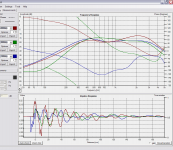
Diagrams:
00 dipole
10 wideband cardioid
20 wideband cardioid having somewhat higher rear rejection from 70...140Hz
30 cardioid having higher rear rejection 70...140Hz
Colors of Graphs:
Red.....: 00 degrees (front)
Green..: 90 degrees (side)
Blue....:180 degrees (rear)
Due to in room nearfield measurement, rear rejection has lower value than to be expected in a real freefield measurement.
Measurements are constant voltage, no eq applied.
Kind Regards
Attachments
Last edited:
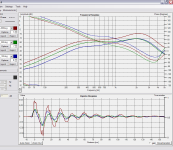
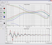
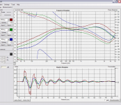
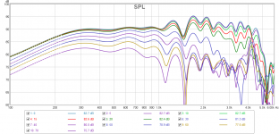
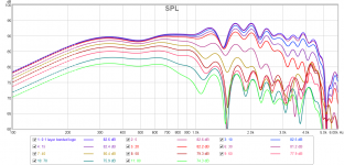
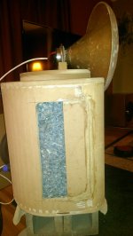
I had a nice day here a few weeks ago so I thought I'd get back out in the garage. I've been wanting to move my vents back to see if I can get less influence near 1khz like was discussed in the last few posts. I moved the vents from the original location (4" wide vent starting 3" behind the baffle plane) back 4" so they're now 7" back. If anyone is interested I can get a pic.
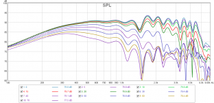
The first plot is my original vent location, the second is with the vents moved back, and the third is of the TD15 in a sealed cab for comparison. You can see that the response is smoother around 1khz with the vents farther back and the directivity is closer to the monopole. Down around 300hz the new vent location has a bit wider response than the old. I think it's interesting that the monopole appears to have a narrower pattern from 500-900hz. This tells me that my vents are still having a bit too much influence, but with the backs of the these cabs curved I don't have the motivation/nice weather to make curved pieces to fit 🙄
The important result here is I'm able to get a better directivity match to my wg. It was rather abrupt before but now it's nice and smooth.
Attachments
natehansen66 said:If anyone is interested I can get a pic.
Hi,
yes, pics would be nice IMO. Maybe even "before" and "current" if possible, so readers would get an impression in one single post, about what has been changed ... 😉
natehansen66 said:Down around 300hz the new vent location has a bit wider response than the old. I think it's interesting that the monopole appears to have a narrower pattern from 500-900hz.
If the uppermost and the lowermost curves represent the same angles in all of that 3 pictures, then IMO what you call "wider" means "wider spread curves", right ?
But "wider spread cirves" due to same interval of angles measured, would mean a "narrower radiation pattern":
So where you say "wider pattern" (of curves ?) i would talk about "narrower pattern" (of radiation), or is there a misunderstandig from my side ?
Last edited:
Hi,
yes, pics would be nice IMO. Maybe even "before" and "current" if possible, so readers would get an impression in one single post, about what has been changed ... 😉
If the uppermost and the lowermost curves represent the same angles in all of that 3 pictures, then IMO what you call "wider" means "wider spread curves", right ?
But "wider spread cirves" due to same interval of angles measured, would mean a "narrower radiation pattern":
So where you say "wider pattern" (of curves ?) i would talk about "narrower pattern" (of radiation), or is there a misunderstandig from my side ?
I'll get a pic up later.
When I say wider response I am talking about a wider pattern around 300hz. If you look at the middle set (which is the new vent location) I forgot to take out the 80deg curve........which isn't present in the other two sets. With a quick looks it appears to be a wider spread meaning narrower pattern 🙄
...
In fact I find the whole idea of striving for directivity down to a few hundred Hz kind of a waste of resources. Which is why I don't do it.
Hi Earl,
when talking about the range above Schroeder Frequency, i do not think that too much "resources" are needed, to have e.g. a cardioid directivity pattern.
When it comes down to LF-sources, then the increase in displaced volume - which is kind of interchangeable with "resources" IMO - when using dipoles or cardioids has to be payed, that is for sure.
And in the modal region there are different factors to discuss and even more opinions ...
One concept to "virtually get rid of modes", is the "double bass array" IMO, where the room's dimensions of wave propagation are virtually reduced to a single one (longitudinal axis of the room) and a "source and sink" system is established, at the same time maintaining the notion of a "wave front" ...
When stating that "steady state response only" counts at LF, we could also rely just on a single subwoofer and use one of the now very popular and also cheap(!) "DCR"-DSP (*) boxes to EQ just the listening seat to flat steady state response. (**) (***)
In upper bass and midrange, "higher DI" e.g. using cardioids is doable. If that - affordable IMO - increase in cost is invested in the speaker, there will be less problems with excess energy at upper bass, lower midrange, and midrange in many rooms. The room's reflections being "too dull", having excess LF to midrange content is IMO one of the most common problems in living room's acoustics. And it can be solved at the loudspeakers in a more cost saving and elegant way, than using excessive room treatment, which gets more difficult, "clumsy" and expensive as you move to larger wavelengths of sound. This IMO holds for both absorption or diffusion ...
Kind regards
_____
(*) btw. i hate the term "Digital Room Correction" in this context, because it is "listening seat dependent equalization" at best IMO ...
(**) but IMO also things like modulation transfer function are important to have audibly "good bass" in a living room e.g.
(***) Wooden houses with larger living rooms, as found in many parts of the US, seem more benign due to LF modes and may provide more passive absorption, than hard walled living rooms. This could be a "source of disagreement" what seems to be "the very best solution" due to LF.
Last edited:
natehansen66 said:If you look at the middle set (which is the new vent location) I forgot to take out the 80deg curve........which isn't present in the other two sets.
...ah, now i see the difference 😉 .
What would be interesting IMO, is whether there is any change in efficiency in terms of excursion needed e.g. below 200Hz to get the same on axis SPL.
THD measures would be quite instructive for this, as making the dipole path length longer should reduce the displaced volume needed for the (excursion intensive) dipole component.
Btw. will you use that speaker as a kind of "satellite" in a Sub/Sat system or which lower cutoff frequency are you aiming at aproximately ?
Kind Regards
I'll look into the distortion data.
These are currently hi passed at 100hz. There's a couple 15" flanking woofers (one per channel)behind the mains covering 50-200, and there's two subs from 20-90. The flanking woofers and mains are both -6dB in the overlap region and with a bit of delay I have a flattish response in the midbass and more headroom. This setup isn't complete by any means. The integration with the flanking woofers needs work.
These are currently hi passed at 100hz. There's a couple 15" flanking woofers (one per channel)behind the mains covering 50-200, and there's two subs from 20-90. The flanking woofers and mains are both -6dB in the overlap region and with a bit of delay I have a flattish response in the midbass and more headroom. This setup isn't complete by any means. The integration with the flanking woofers needs work.
I think that electronic polar shading will be the future of low frequency enclosure design. Enough of this "T-S QB3" (insert current vogue here) alignment nonsense. It's the pattern that matters NOT the response. One just EQs the response in-situ anyways.
The future seems to be here: BeoLab 90 - Bang & Olufsen high-end vloerluidspreker. - Bang & Olufsen
I'll hold off my opinion until I see some valid data for those. They meet all the expectations of marketing, that's for sure, but marketing isn't always the best indicator of performance.
Try this page:
B&O Tech earfluff and eyecandy
B&O Tech: What is “Beam Width Control”? earfluff and eyecandy Here are some measurement, but I remember seeing better plots elsewhere on the site.
B&O Tech earfluff and eyecandy
B&O Tech: What is “Beam Width Control”? earfluff and eyecandy Here are some measurement, but I remember seeing better plots elsewhere on the site.
- Status
- Not open for further replies.
- Home
- Loudspeakers
- Multi-Way
- DSP midrange directivity control aka kinda cardioid