I don't think that this is true, in fact theoretically it is definitely not true. Four sources (or two) with DSP simply has more degrees of freedom
Oh, we don't disagree on that side- I was specifically talking about the variant shown- where the key difference between it and the slots was the effectively omni dispersion of the DSP version below 200, compared to the more directional behavior of the sloted case.
My point was that the DSP variant, in this case, would maximize modal excitation, and thus was better aligned to your preferred multi-source modal-maximization bass arrangement.
Is there an advantage to "maximal mode excitation" under 200 or 300hz from a single monopole? I thought the point was for distributed sources in the modal region? Or is it room dependent? Difficult to do around 200hz where we can't run a sub. I'm personally using flanking woofers from 60-300 hz to good effect. Pretty good midbass smoothing compared to a single driver, though I think 300 might be too high for the distance they're separated.....
Nate:
Yes, maximum modal excitation from each source allows one to "fill in" with placement to maximum efficacy- the more modes the mains excite, the better you can target the additional subs to excite the other modes.
Yes, maximum modal excitation from each source allows one to "fill in" with placement to maximum efficacy- the more modes the mains excite, the better you can target the additional subs to excite the other modes.
My point was that the DSP variant, in this case, would maximize modal excitation, and thus was better aligned to your preferred multi-source modal-maximization bass arrangement.
I thought that the modal excitation dependence on the source type was put to rest - there really isn't one. All modes are excited by all sources, just to a greater or lessor degree depending on location. But if one takes and looks at several different locations then all source types come out pretty much the same. Monopoles do tend to favor placement near surfaces and dipoles placement away from surfaces, but that is about all you can say. I've done several papers and studies on this.
Of course monopoles are much more efficient at LFs and that is a good reason to go monopole very low, which implies using DSP, but I don't think that it is a modal excitation issue. To me the concepts of modal excitation and efficiency are independent. One, efficiency, sets the mean level, while the other determines the variations about the mean. We can globally correct the mean, but not the variations about it.
Last edited:
Monopoles do tend to favor placement near surfaces and dipoles placement away from surfaces, but that is about all you can say. I've done several papers and studies on this.
and hyper-cardioid favors both placements and everything between which indicates that your papers might be quite worthless.
kimmosto, your web page is quite interesting and was partly inspiration for this project. That said how can you prove your statement? It may be the case in some rooms but to say that's the case for *every* situation seems to me a bit of a stretch.
I thought that the modal excitation dependence on the source type was put to rest - there really isn't one. All modes are excited by all sources, just to a greater or lessor degree depending on location. But if one takes and looks at several different locations then all source types come out pretty much the same.
It seems to me that a directional bass would take longer to excite lateral modes, and there would be attenuation associated with that- meaning less excitation. I could be wrong. We're getting pretty deep in the weeds here, as we're not debating goals or even methods but sub-methods (sub methods... hur hur hur) 😀
It may "take longer" to excite the lateral modes (assuming the bass is directed longitudinally) but this is insignificant since the modes will have established themselves in just a few cycles so this is a few ms difference at most. I cannot see how our ears could be sensitive to times like this at LFs.
But yes, this is 'frosting on the cake": the whole modal structure makes far more difference than any of this other stuff. By that I mean that every room is different and nothing global can really be said. Each room needs to be individually setup regardless of the "type" of source being used.
Hyper-cardioid is just the sum of a monopole and a dipole just like a cardioid, but with a slightly different ratio than a cardioid, so its results will not be significantly different than that for a cardioid and cardioid was part of the papers that I did. As you might expect it was less sensitive to location, but its best locations were not as good as the best locations of a monopole or a dipole. So in a sense it is less sensitive to location, but all that gets washed away if one uses multiple subs with EQ. Then source type and location both become irrelevant.
Last edited:
So in a sense it is less sensitive to location, but all that gets washed away if one uses multiple subs with EQ.
That's very big "If". Why the heck would I use multiple sources and EQ if they are not necessary. That's total off-topic when discussing differences between source types.
I cannot see how our ears could be sensitive to times like this at LFs.
Ears are not only sensors we have for audio with speakers. I think that skin and other body is the most sensitive sensor for timing issues at LF. I have tested this with earphones; excess group delay at LF is not clearly sensed by (internal) ear but skin around ears senses dropping of energy peaks when excess group delay increases.
So, my conclusion and experience is that better acoustical timing of LF pressure wave is possible to sense, and unidirectional has some benefits because front wall and corners do not send 1st order reflections. Back wall and corners behind listener are still there, but not always as close as front wall to speakers.
Last edited:
kimmosto, your web page is quite interesting and was partly inspiration for this project. That said how can you prove your statement? It may be the case in some rooms but to say that's the case for *every* situation seems to me a bit of a stretch.
"Every" is useless theoretical limes. I would say: if you have 69% chances to get adequate flat response, good timing, equal level and neutral balance on large area in any room without room EQ and electrical level adjustment, it would be a smart move to try at least twice in a lifetime. No need to marry - just try and evaluate.
Already told that it's not perfect, needs shelving LP and SPL capacity is limited without large drivers.
That's very big "If". Why the heck would I use multiple sources and EQ if they are not necessary.
You wouldn't, except that is not reality. I can always improve the situation with more subs. But if "adequate" is good enough for you then sure, multiple subs is not necessary. I am 100% sure that multiple subs can achieve "optimal".
It's very good that you have at least some tools to improve your poor basic setup. I'm afraid that "optimal" is never achieved here because my slightly damaged & sensitive ear doesn't like right side and rear sources. Hopefully "the best" would be adequate.
There has been a study, recently completed in fact, that showed how our brain needs LF timing to be correct in order to process musical content satisfactorily ... and it was not gender specific. This was outlined on an NPR show within the last few weeks if I recall correctly. I'll see if I can find out more.Ears are not only sensors we have for audio with speakers. I think that skin and other body is the most sensitive sensor for timing issues at LF. I have tested this with earphones; excess group delay at LF is not clearly sensed by (internal) ear but skin around ears senses dropping of energy peaks when excess group delay increases.
So, my conclusion and experience is that better acoustical timing of LF pressure wave is possible to sense, and unidirectional has some benefits because front wall and corners do not send 1st order reflections. Back wall and corners behind listener are still there, but not always as close as front wall to speakers.
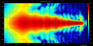
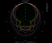
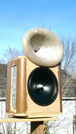
So I haven't ditched this project yet. I've got one cab that I intend to use ready for testing. I wanted to try out bending mdf, so I added a 3" radius to the side corners of the baffle, and a large 12" radius corners on the rear. This effectively changes the distance from the baffle plane to my side vents. With the 3" radius roundover that distance works out to about 4.5" which is 1/4wl of 750hz. The idea is to smoothly transition from the cardioid pattern to the piston diameter narrowing the dispersion. This seems to have worked out quite well I think. You can see from the full polar plot that (at least for the angles I can view in ARTA) these are not a perfect cardioid.......at all! They do control the directivity well though. From 300hz up there is about 10dB and greater rejection to the sides and rear. Not too shabby but more would be better.
I measured them about 7' off the ground to the bottom of the cab with the mic about 8' away.....7.5ms gate. GP would be better but I wanted to measure my waveguide as well and work out a xo. Unfortunately it got a little breezy so I'm not confident in the wg measurements.
There's a +5dB low shelf at 200hz to bring up the low end. I measured at about 80-85dB and there's visually quite a bit of excursion compared to a sealed cab, which is to be expected. When I use these in my room I have additional flanking woofers from 200hz down so I won't apply the full 5dB of boost. Maybe I won't boost at all......we'll see how they look in room.
Attachments
I would believe that the closer the slots are to the baffle, the narrower pattern. They can even start in the baffle in extreme circumstances
Hello,
this would mean decreasing the dipole path length of the cabinet considerably.
But in such a construction (OB dipoles, resistance boxes etc. ...) it is wise IMO to have the dipole path length as long as possible (but not any longer...), to save needed excursion of the driver at low frequencies.
On the other hand dipole path length should not get longer than about lambda/3 at the upper end, otherwise the dipole pattern degenerates. This is assuming a driver, which is a point source being small(!) compared to wavelength.
But when using a rather large LF driver, as it is the case here, the driver's "own" directivity will narrow the radiation pattern at mid and higher frequencies without the resistance box itself contributing too much here.
You can even afford then making the dipole path length considerably longer than needed for maintaining the dipole pattern in the (upper) crossover region (at about 900Hz in this example here ?).
Example:
---
IMO a "sane" dimensioning could be e.g. to have "F equal" about 1 octave above the lower crossover frequency. That means, if e.g. 100Hz is the desired lower crossover frequency, you can make the dipole path length such to have on axis SPL equal to a monopole box at 200Hz (Feq = 200Hz).
That means the driver needing only 2x the excursion at 100Hz, to have same SPL on axis than in a monopole cabinet.
On the other hand the dipole pattern will then degenerate at about 400Hz, which means that side lobes would start to develop unless the driver's own directivity gets dominant.
---
In most cases i see in DIY cardioids, the dipole path length is chosen too short, which causes unecessary high excursion at LF.
If less radiation to the sides is desired, then one could go towards the hypercardioid pattern, which has a small antiphase lobe to the rear and significantly less radiation to the sides.
That pattern can be formed e.g. by lowering the resistance component in the slits of a resistance box and thus moving the pattern slightly towards a dipole alignment.
If on the other hand the dipole path length at a given frequency is significantly smaller than about lambda/3, the dipole pathlength itself cannot be used to change the radiation pattern significantly by making it even smaller:
Either you have a "proper" dipole-8 (or cardioid) pattern or not. There is no "further narrowing" by decreasing the dipole path length. Only thing happening is "paying more excursion" for the same SPL.
Of course it will also maintain the dipole-8 (or cardioid) pattern up to dipole path length being about lambda/3.
As been said using larger drivers dipole path lengths can be made larger too, as long as the baffled driver itself has a DI (say ...) coming close to that of a dipole/cardioid pattern at "dipole path length" = lambda/3.
The DI of a dipole or cardioid is about 4.7dB.
If the output of the slits is considerably low-passed at "dipole path length" = lambda/3 already and the baffled driver's own DI comes close to the cardioid pattern, a smooth transition between the "cabinet controlled" and the "driver controlled" pattern can be established.
Beaming of the driver itself and cone breakup will now put a limit to the upper crossover frequency, but not the cabinet's alignment itself.
Kind Regards
Last edited:
If less radiation to the sides is desired, then one could go towards the hypercardioid pattern, which has a small antiphase lobe to the rear and significantly less radiation to the sides.
A dipole has zero radiation to the sides (it has nulls), but a cardioid/hypercardioid does radiate to the sides, so how can this statement be true? Further a cardioid has a single anti-phase null at the rear, while a hypercardioid has two nulls "near" the rear but no null right at 180 degrees.
Estimation of "Fequal" for dipoles:
http://www.linkwitzlab.com/spl_max1.xls
Another kind of "art" is estimating the effective dipole path length from a cabinet's or baffle's geometry ...
H-U frame woofers
http://www.linkwitzlab.com/images/graphics/Cpract1.gif
It is not estimated by using the path from center of the driver to the center of the slit of the "mechanical resistor".
On a circular dipole baffle having a small driver in the middle, the dipole path length would be from the center of the baffle to the edge.
In a typical cardioid PA woofer, the path component from the driver to the edge of the baffle counts only once (mostly in a PA cardiod subwoofer you have also a driver at the rear baffle) and is added to the depth of the cabinet: That is shorter than going from "front driver center" to "rear driver center".
A dipole has zero radiation to the sides (it has nulls), but a cardioid/hypercardioid does radiate to the sides, so how can this statement be true? Further a cardioid has a single anti-phase null at the rear, while a hypercardioid has two nulls "near" the rear but no null right at 180 degrees.
Hi Earl,
first wishing a happy new year to you(!),
i was writing about the hypercardioid pattern having "less" radiation to the sides than the cardioid (maybe this was not made clear enough). I was not writing about where the nulls are ...
But IMO the statement "a hypercardioid has less radiation to the sides than a cardioid" is still true, even though the nulls are near the rear.
So there is no contradiction IMO, as there is an intermediate transition of patterns from cardioid to dipole and vice versa.
Even around 90 degrees off axis ("to the sides"), the hypercardioid is a bit "quieter" than the cardioid:
http://eaw.com/docs/ZZ_Web_Media/Technology_Graphics/Subwoofer_Arrays/Subwoofer_paper3.png
http://en.wikipedia.org/wiki/Microphone#Microphone_polar_patterns
Kind Regards
Last edited:
Hi Earl,
first wishing a happy new year to you(!),
i was writing about the hypercardioid pattern having "less" radiation to the sides than the cardioid (maybe this was not made clear enough). I was not writing about where the nulls are ...
Kind Regards
Same to you.
My mistake, I see what you mean now. I thought you were talking about dipoles versus cardioid. Hyper-cardioid will have less radiation to the sides than cardioid - correct. I believe that Hyper-cardioid has the highest DI of all the configurations - something like that (getting too old to remember this stuff!)
- Status
- Not open for further replies.
- Home
- Loudspeakers
- Multi-Way
- DSP midrange directivity control aka kinda cardioid