xrk971 - you would have to show me how this is possible theoretically. I have a great deal of expertise in nonlinear systems and I am telling you that what you claim to be happening is not physically possible.
And I think that we may be arguing different things. If you are saying that the walls of the horn as so thin that they are flexing at fairly large amplitudes, then yes, the generation of random noise and some harmonics is possible. But I cannot conceive of why anyone would want to do that, so I had not considered this case. For the physical structure of a waveguide to move in a manner that was nonlinear it would have to exhibit either a geometrical nonlinearity - like a pendulum under large displacements - or a material nonlinearity, like a rubber band stretched to its limits where its stiffness increase faster than Hooke's law suggests. These are very large displacements and only an extremely flimsy waveguide would ever even come close to this being the case. Since such a case is far from useful, I would simply discount the example as being of any relevance to our subject here. It would be like making an enclosure out of cardboard and then wondering why things don't work very good.
And I think that we may be arguing different things. If you are saying that the walls of the horn as so thin that they are flexing at fairly large amplitudes, then yes, the generation of random noise and some harmonics is possible. But I cannot conceive of why anyone would want to do that, so I had not considered this case. For the physical structure of a waveguide to move in a manner that was nonlinear it would have to exhibit either a geometrical nonlinearity - like a pendulum under large displacements - or a material nonlinearity, like a rubber band stretched to its limits where its stiffness increase faster than Hooke's law suggests. These are very large displacements and only an extremely flimsy waveguide would ever even come close to this being the case. Since such a case is far from useful, I would simply discount the example as being of any relevance to our subject here. It would be like making an enclosure out of cardboard and then wondering why things don't work very good.
Also - looking at your data, it is said that the lowest graph has .088% THD, which is an incredibly low figure for any loudspeaker. This alone is highly suspect.
Gedlee,
The HD is extremely low because the coupling between the driver and the air via the tractrix horn is so efficient, that the cone only needs to move about 40 micrometers (according to predictions) to generate 95dB of SPL. The microscopic amount of cone motion is what makes the low distortion possible. I have stuck my fingers into the throat of this horn and touched the cone, and indeed the movement is hardly perceptible by touch, yet it is deafeningly loud. That is one reason why I say it is one of the cleanest sounding speakers I have ever heard. This was using a Dayton UMM-6 which has a higher self-noise than the current UMIK-1 I am using. Both are calibrated and I am pretty confident the HD measurement is what it is.
More info on this tractrix horn here in this thread:
http://www.diyaudio.com/forums/full-range/259293-prv-5mr450-ndy-fast-applications-13.html
I know what you are saying, unless the transfer function from excitation to generation is non-linear, you cannot generate harmonics. There may be some properties of the bend modes in the flexing of walls of the foam core that is non-linear with respect to applied excitation. Cantilever bend displacement is non linear with beam length for example. Just compression of air in the small pre-chamber of the horn throat is a non-linear process, although maybe small effect.
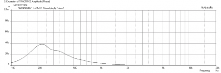
Here are predicted SPL and Cone Displacement for the 5MR450NDY driver in the tractrix horn:
The HD is extremely low because the coupling between the driver and the air via the tractrix horn is so efficient, that the cone only needs to move about 40 micrometers (according to predictions) to generate 95dB of SPL. The microscopic amount of cone motion is what makes the low distortion possible. I have stuck my fingers into the throat of this horn and touched the cone, and indeed the movement is hardly perceptible by touch, yet it is deafeningly loud. That is one reason why I say it is one of the cleanest sounding speakers I have ever heard. This was using a Dayton UMM-6 which has a higher self-noise than the current UMIK-1 I am using. Both are calibrated and I am pretty confident the HD measurement is what it is.
More info on this tractrix horn here in this thread:
http://www.diyaudio.com/forums/full-range/259293-prv-5mr450-ndy-fast-applications-13.html
I know what you are saying, unless the transfer function from excitation to generation is non-linear, you cannot generate harmonics. There may be some properties of the bend modes in the flexing of walls of the foam core that is non-linear with respect to applied excitation. Cantilever bend displacement is non linear with beam length for example. Just compression of air in the small pre-chamber of the horn throat is a non-linear process, although maybe small effect.
Here are predicted SPL and Cone Displacement for the 5MR450NDY driver in the tractrix horn:
Attachments

Last edited:
Cantilever bend displacement is non linear with beam length for example.
But it is linear with displacement amplitude, hence it is a bad example of your point. For bending waves to be nonlinear - they are assumed to be linear in virtually all cases - there would have to be a material nonlinearity in the stress-strain (there is no geometric nonlinearity possible) and this would take a lot of displacement.
I have measured a few horns myself and .08% THD is simply unheard of in an acoustic system. Horn can often reach as high as >10% in operation - that's 1000 times higher than what you are showing. AND the THD always rises at LFs and yours does not. I'm sorry, I just can't buy your example as being valid. It doesn't past the test of reasonable.
There is no need for the waveguide material to be non-linear. For example, if the waveguide walls are moving in and out together at the same same frequency as the radiated sound then, compared to the rigid wall case, the sound will be louder during the inward phase and quieter during the outward phase. This will contain harmonic distortion relative to the rigid wall case even if the motion of the boundaries is linear. The key is that the displacement must be significant in order to make the sound louder and quieter. It cannot be tiny/virtual which is often the assumption with linear acoustics.But it is linear with displacement amplitude, hence it is a bad example of your point. For bending waves to be nonlinear - they are assumed to be linear in virtually all cases - there would have to be a material nonlinearity in the stress-strain (there is no geometric nonlinearity possible) and this would take a lot of displacement.
I have measured a few horns myself and .08% THD is simply unheard of in an acoustic system. Horn can often reach as high as >10% in operation - that's 1000 times higher than what you are showing. AND the THD always rises at LFs and yours does not. I'm sorry, I just can't buy your example as being valid. It doesn't past the test of reasonable.
I have made many horns and speakers too, and yes, 0.08% THD is extremely low - but not unheard of and doesn't always happen. This is indeed a special speaker. But just because you have not heard one, doesn't mean it can't be done.
You should listen to the sound clips from that thread. Perhaps you are biased as you use CD's to drive your horns. This is achieved with a 5in Nd motor with copper shorting rings, pro-audio 95dB sensitive mid driver coupled to a tractrix horn. Low HD distortion measurements this low are rare - certainly, my usual direct radiator (open faced) speakers never measure this low. Again, I submit it is because of only needing 40 microns of displacement to achieve the desired SPL. Believe it or not but the data is there and the sound clips are there for all to see/listen too.
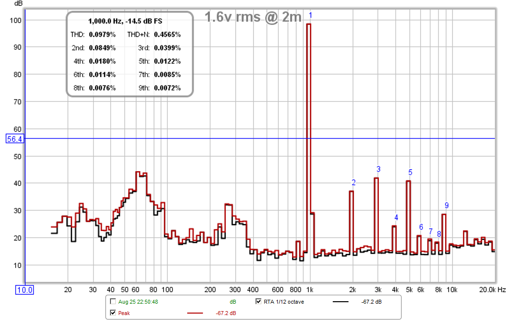
Here is RTA with 1kHz excitation, 0.1%THD at 98dB SPL at 2m distance and 1.6 volts, THD+N is 0.456%:
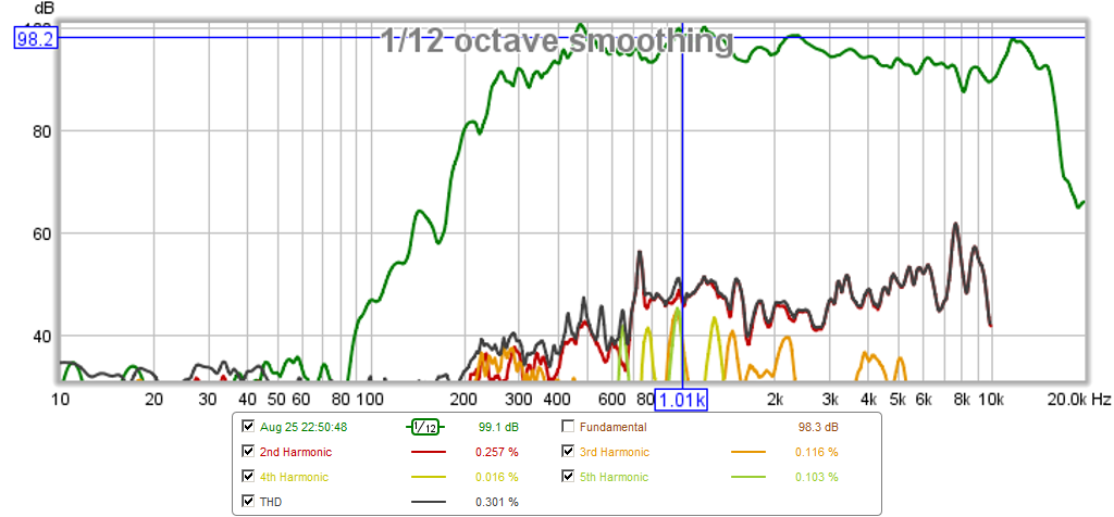
Corresponding freq resp:
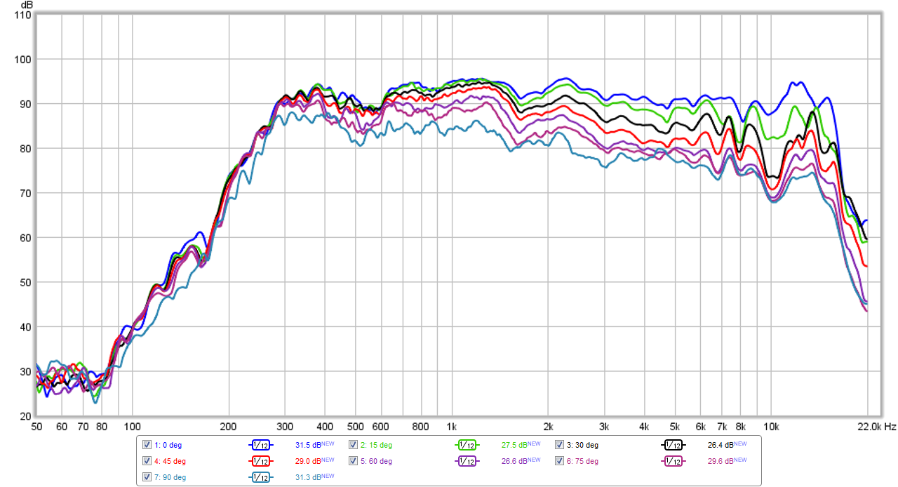
Corresponding polar response measurement:
Listen to the sound clip from this speaker, does that sound like 10% or even 3% THD?
http://www.diyaudio.com/forums/atta...dy-fast-applications-tractrix-cld-clip-04.zip
Last edited:
andy19191 - you are correct, but that's grabbing at straws. Way beyond the case for reasonable.
xrk971 - I remain unconvinced. THD that rises with frequency and is negligible at maximum cone excursion is just not realistic.
xrk971 - I remain unconvinced. THD that rises with frequency and is negligible at maximum cone excursion is just not realistic.
Again, you are comparing to your norm of a CD where HD is rising at bottom. This tractrix is providing horn loading down to 175Hz and I have a high pass filter at 400Hz. The fs is 175Hz. HD rises if you push the cone to an excursion that is large relative to its xmax. Given that xmax is 2.5mm and it is moving only 1.6% of its xmax, it should not be hard to see why HD is low. What is diaphragm displacement in % of xmax for one of your CD's in your waveguide at its low frequency corner? Is it less than 2% xmax? Look at how this system may be different and you may be able to see how something can work like this.
The data is there and all you have to do is have an open mind as to how this can be and not close off with absolutes of "this cannot be so." It's rather silly how close minded something like that is.
I am not going to argue with you anymore as you are set in your beliefs. That's too bad. Just hope others here may look to trying CLD as a means to lower HD in their horns and to give cone drivers in a horn a try. They sound much better than normal direct radiator speakers.
Last edited:
Again, you are comparing to your norm of a CD where HD is rising at bottom. This tractrix is providing horn loading down to 175Hz and I have a high pass filter at 400Hz. The fs is 175Hz. HD rises if you push the cone to an excursion that is large relative to its xmax. Given that xmax is 2.5mm and it is moving only 1.6% of its xmax, it should not be hard to see why HD is low. What is diaphragm displacement in % of xmax for one of your CD's in your waveguide at its low frequency corner? Is it less than 2% xmax? Look at how this system may be different and you may be able to see how something can work like this.
The data is there and all you have to do is have an open mind as to how this can be and not close off with absolutes of "this cannot be so." It's rather silly how close minded something like that is.
I am not going to argue with you anymore as you are set in your beliefs. That's too bad. Just hope others here may look to trying CLD as a means to lower HD in their horns and to give cone drivers in a horn a try. They sound much better than normal direct radiator speakers.
I would agree, and thanks kindly for all that you share with us here.
xrk971 - then all I can say is that you have invented the greatest speaker ever made. You should market it.
Age and experience makes me very skeptical of over-the-top claims like this however. Its a result of over 50 years experience.
Age and experience makes me very skeptical of over-the-top claims like this however. Its a result of over 50 years experience.
Lively discussion on multiple subjects.....
Excuse interrupt but back to laminating and applied damping materials:
Andy, Andrex ...thanks for the info.
Had to get my head around the vacuum press .... Assuming your referring to 'vacuum bagging' which initially seems very counterintuitive would be very useful for a lot of applications.
But I have to argue that all it does is remove air(under atmospheric pressure) from inside so that the force of atmospheric pressure outside can be applied directly against the material inside. Thus it's limitations: The theoretical limit being set by the atmospheric pressure relative to vacuum (approximately 14.7 psi sea level, planet Earth). Excusing our dumb units of measure, that's 2,117 lbs/ft2. Matching achieved estimates I've seen posted for vacuum presses of app. 1,800lbs/ft2.
OK, sounds like a lot but far below the stated specs of some adhesives I've seen. So, method being dependant on your choice of adhesive..... Certainly beats my initial process.
On the use of common roofing materials for applied damping, I'd strongly argue that anything containing petroleum distillates be avoided for same reason as not using common MDF (contains formaldehyde) because of eventual damage to rubber/foam speaker surrounds from outgassed hydrocarbons....which is more common than most think.
Claiming experience over empirical data asks a lot around here. It also exposes one to their own history. While I personally see Mr. Geddes is one of the better acoustics designers around (his patents, papers and ground breaking research of HOMs and 1P equations bear this out) he is still as much a human as the rest of us.
In 2008 Earl Geddes wrote (about tapped horns):
"John
That just looks like a badly tuned bandpass. Why not just build a bandpass? They have worked well for me. "
and
"I looked at the tapped horn briefly and I agree that to me it was a transmission line. Horns at low frequencies, like in your example, just don't work as horn. They are too small and only act as very big ports. Of course big ports are a good thing - lower loss - but a straight port is a lot easier to build if it works the same as a horn. "
You can read his posts and decide for yourself if 43 years of experience is enough to quickly judge other designers innovations as non-novel or unimportant. Here is the thread from 2008:
http://www.diyaudio.com/forums/subwoofers/114340-tapped-horn-dummies-3.html
@ Geddes, I respect your work, but pulling the "My experience trumps your measurement card" doesn't facilitate understanding or development. Why not build one of these tractrix horns? I have 4 of the 3fe22 variant of this XRK tractrix and they sound pretty good (made from wood). The foamcore version is easy enough to make.
Working in live sound I can say that midrange from cones in horns (like funktion-1 and turbosound use) are a lot cleaner than compression drivers, unless we're talking something crazy like the community M4.
Here is RTA with 1kHz excitation, 0.1%THD at 98dB SPL at 2m distance and 1.6 volts, THD+N is 0.456%:
You have a software problem. 3HD alone is over 0.15% on that graph, nowhere near the 0.0399% in the table.
5HD is just as high, and more than 10x higher than depicted in the table. (Aside: the Geddes Distortion Audibility of this horn might be high-ish.)
Who knows what is going on there, and how deep the measurement issue goes?
I looked at the tapped horn briefly and I agree that to me it was a transmission line.
That is true if you use TL in the broad sense. It is only a horn in that it expands. It is a limited bandwidth quarter-wave resonator.
dave
I agree ! Especially a lower quality mid-horn.... I can say that midrange from cones in horns (like funktion-1 and turbosound use) are a lot cleaner than compression drivers.....
Repeating myself:
......those EV 8HD/1823M midrange horn/drivers have to Go......Yuk, for sale cheap !
Maybe back when it all tubes and 15"-30" woofers were stuffed in a box without regard to any parameters....when midrange cones couldn't be even heard horns ruled the day.
ie. My father's stuffed so called 'folded horn' cabinet

Last edited:
You have a software problem. 3HD alone is over 0.15% on that graph, nowhere near the 0.0399% in the table.
5HD is just as high, and more than 10x higher than depicted in the table. (Aside: the Geddes Distortion Audibility of this horn might be high-ish.)
Who knows what is going on there, and how deep the measurement issue goes?
3HD and 5HD are visually about -55dB to -60dB below the 1kHz peak. The math seems right to me as -60dB is 0.1%. Nothing wrong with the software.
Last edited:
xrk971 - then all I can say is that you have invented the greatest speaker ever made. You should market it.
Age and experience makes me very skeptical of over-the-top claims like this however. Its a result of over 50 years experience.
I can't claim any credit to inventing the tractrix with a cone driver - inspiration came from Bruce Edgar's horn and the profile was calculated using Ed Forker's spreadsheet - all detailed in my thread. Perhaps the innovation was making it out of foam core and using a full range driver vs a mid range driver and using CLD by adding a second layer of foam core glued on with lots of latex caulking. Commercially though, paper cone driven mid horns are the foundation of Funktion 1 and part of why their systems sound so good. So really I never thought what I was measuring in terms of low distortion as new. It's known to those who employ mid horns that they sound clean for this reason - cone excursion is exceedingly low.
3HD and 5HD are visually about -55dB to -60dB below the 1kHz peak. Nothing wrong with the software.
Please don't be obtuse. That's insulting. They are both higher than 2HD on the graph, yes? What % number is 2HD on the table?
Please don't be obtuse. That's insulting. They are both higher than 2HD on the graph, yes? What % number is 2HD on the table?
Not trying to be obtuse at all. Your statement:
is insulting, when it's you that doesn't know how to read a graph correctly.Who knows what is going on there, and how deep the measurement issue goes?
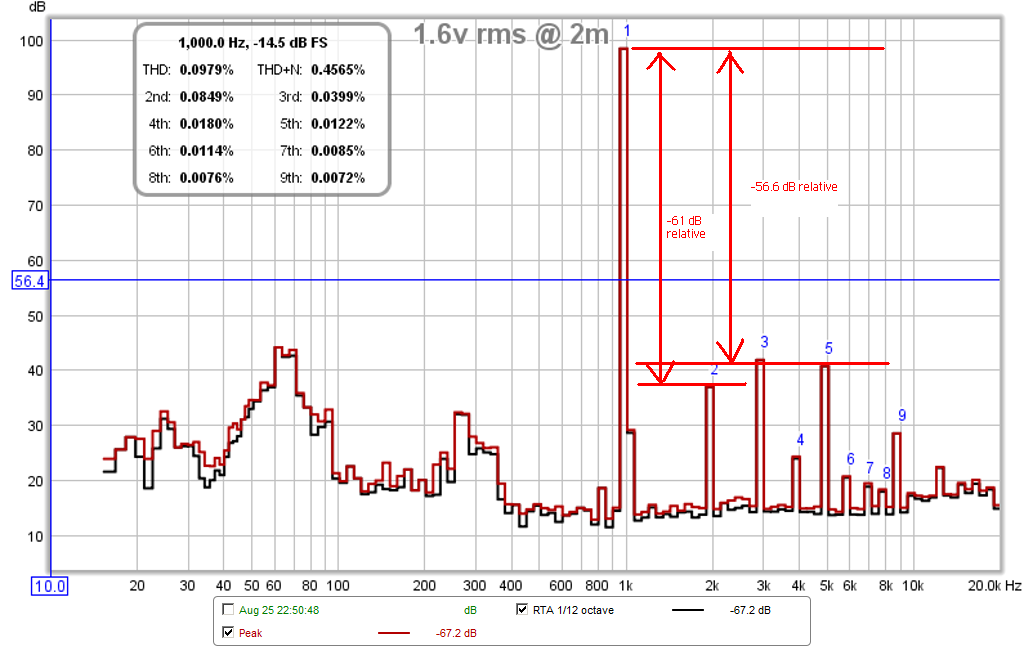
The 2HD on the graph visually appears about a little more than -60dB below the fundamental, that is consistent with a value displayed as less than 0.1%.
According the manual for REW (page 123), the distortion measurements using the RTA are calculated as follows:
Harmonic Distortion
Harmonic distortion results are only valid when the system being monitored is driven by a sine wave
at a single frequency. The highest peak is used to determine the fundamental frequency of the input, this
is displayed with the level of the fundamental. The THD figure is based on the number of harmonics whose
levels are displayed and is calculated from the sum of those harmonic powers relative to the power of the
fundamental. The THD+N figure is calculated from the ratio of the input power minus the fundamental
power to the total input power (note that it is possible for THD+N to be lower than THD using these
definitions). The example below shows data for a 1kHz sine input. The positions of the harmonics are
shown on the spectrum or RTA plot.
The key word is *relative* levels.
Attachments
Last edited:
That is true if you use TL in the broad sense. It is only a horn in that it expands. It is a limited bandwidth quarter-wave resonator.
dave
If it has a taper, then it's a 1/2 WL resonator with a 1/4 WL fundamental with both even and odd harmonics same as any other horn, though due to the nature of the design it only has actual horn loading above the tap point, but with a rapid phase rotation it's mostly useless: Resonances of open air columns
GM
- Home
- Loudspeakers
- Multi-Way
- The best cabinet material !!!!