In the February 1979 issue of "Sound and HiFi" magazine (Sound & Vision nowadays) there is an article by Theodoros Spinoulas presenting the construction of a satellite-subwoofer system using T27,B110 (for satellites) and B139 for the sub.You may ask if they still have an issue to buy,otherwise they can grant you photocopies.
Last edited:
If you are going to put B139 in a TL i would suggest one designed using proper modeling instead of vintage lines which were as much guess as anything else.
There are some variations on the same modern line here: Transmission Line Speakers
dave
There are some variations on the same modern line here: Transmission Line Speakers
dave
Thank you for your suggestions. Kimon, I will have a look at my uncle's mag collection to see if he has a copy. Otherwise I will contact them and see if they got anything.
A somewhat earlier sub/satellite system using the same drivers from Linkwitz is available online: SB1980-3way
This from Wireless World, 1978. I built this system (nearly), back then. It's really quite good.
This from Wireless World, 1978. I built this system (nearly), back then. It's really quite good.
The link doesn't work, it goes "loop" to the home page
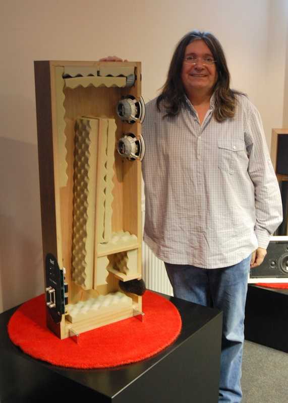
But I guess it's the tall enclosure with the speakers on one side and the walls inside forming
triangular columns !?!
But I guess it's the tall enclosure with the speakers on one side and the walls inside forming
triangular columns !?!
The link works for me.
I see:
Loudspeaker system design
A Three-Enclosure Loudspeaker System
Part 1 - Cabinet design
Part 2 - Electronic crossover and equalization
Part 3 - Changes and refinements
Excursion-Limited SPL Nomographs
Speaker Builder Mailbox
--------------------------------------------------------------------------------------------------------------------------------
Revised from articles first published in Wireless World, London, 1978
If you go to the home page, check pretty far down the left side,
Three-Box active
system (1978)
😀
I was still at page two
And I was referring to this: Triangulated TL
BTW your link...
I do much prefer 1996 artcle with active 3 way in its semplicity ( though I remember the author suggested to get industry matched drivers )
I was still at page two
And I was referring to this: Triangulated TL
BTW your link...
I do much prefer 1996 artcle with active 3 way in its semplicity ( though I remember the author suggested to get industry matched drivers )
In the February 1979 issue of "Sound and HiFi" magazine (Sound & Vision nowadays) there is an article by Theodoros Spinoulas presenting the construction of a satellite-subwoofer system using T27,B110 (for satellites) and B139 for the sub.You may ask if they still have an issue to buy,otherwise they can grant you photocopies.
To koozoop.
I have all issues this magazine in greek if you want ,let me know.
That's great demetrios! Is it possible to scan and send me (koozoop@gmail.com) the aforementioned pages? I would be grateful!
There are no placement measurements for the B110 nad T27 though. Does anyone have plans for this design?
Hmm, the cab dimensions are in the pdf and the woofer is near the top [not hyper critical in this design] with the mids horizontally centered on the woofer with the tweeter directly above it. Don't know if these XO's are suitable or even a good starting point for tweaking: http://p10hifi.net/TLS/classics/images/RadfordXO.gif
Still, as others has noted, measuring your drivers to be able to design an optimum TL is worth the extra effort.
GM
GM, the Radford uses quite different drivers. Goodmans mid & woofer, an Audax (?) tweeter. Googling for pictures i see some use a dome mid instead.
dave
dave
Ah! OK, I just searched for Radford XO's and these were all I found, so posted in the hope it might be at least a good starting point.
GM
GM
As observed earlier, the OP features two very different designs. The seconds looks like the Atkinson Mini-Line from HFN, which featured an Isophon tweeter. The Fris Daline also had a variety of tweeter arrangements.
The decoupled TL idea has cropped up a number of times. Ted Jordan alluded to it in a 1971 Wireless World article and George Augsperger has it as one of his TL alignments in his Speaker Builder articles. The GA alignments may be a good starting point for the B110 if you can get some basic measurements of the units. I built the GA coupled chamber design for a JX92S and it sounded pretty good; it didn't go as deep as a MLTL but wasn't designed to, aiming more for a sealed box size/f3 but with increased power handling.
The decoupled TL idea has cropped up a number of times. Ted Jordan alluded to it in a 1971 Wireless World article and George Augsperger has it as one of his TL alignments in his Speaker Builder articles. The GA alignments may be a good starting point for the B110 if you can get some basic measurements of the units. I built the GA coupled chamber design for a JX92S and it sounded pretty good; it didn't go as deep as a MLTL but wasn't designed to, aiming more for a sealed box size/f3 but with increased power handling.
Or you could put the units in a LS3/5a size cabinet, use an inadequate crossover and claim they are Linn Kan clones 🙂
Last edited:
Hello again. Does anyone have the Klinger book with his KEF speakers? Is it worth buying (I found the 1989 version for €22 and the 1977 one for €30)? Ι'm currently trying to modify David's Triangulated TL (http://p10hifi.net/TLS/downloads/B139-TTL-map-100707.pdf) to fit the B110B and T27 but I'm not sure it will work...
It's been a long time since I created that thread and I haven't managed to build any kit yet! I still have the B110's and T27's along with 2xB139's that I just acquired. So I'm thinking into going for a larger TL speaker like this: http://www.keith-snook.info/wireles...e Transmission-line loudspeaker Enclosure.pdf.
There are no placement measurements for the B110 nad T27 though. Does anyone have plans for this design?
Thank u in advance!
Keith-Snook list a lot of Wireless World articles, but it appeared to me that the link to the actual articles were broken. Were you able to get the 1972 Wireless World article on Transmission Line Speaker by Arthur Bailey yet? It has every detail of the cabinet you need to build the speaker. You should also get the original article by Bailey in the 1965 Wireless World where Bailey explained why his TL must use Long Fiber Wool for stuffing and polyester or fiber glass stuffing does not work. When constructed properly, it is still one of the best quality bass you can get with the KEF units.
The crossover question is easier, Falcon Acoustics still have the standard design in stock, with a super tweeter section at various quality (price) points. Both the crossover #6 or #33 will work for you.
Loudspeaker Crossovers, Networks, Filters, LS3/5a, KEF, most makes.
You can see the Webb TL article for the crossover component values.
Speaker Construction Articles - Archive/Links/History/Tips
For long fiber wool, Bailey meant the cheaper coarse wool used for industrial application. The fiber should be 5 inches long or longer. The more expensive wool for sweater or clothing is too fine to work properly. You can ask for comforter wool at a woolen mill which will be close to what you need. Buy it cleaned, carded.
Good luck.
1972 Wireless World article on Transmission Line Speaker by Arthur Bailey yet? It has every detail of the cabinet you need to build the speaker.
You can even get a dimensioned drawing (not in the article) on my TL website (in the Classics section).
But is is an antique, by guess & by golly, design. The one he is working with is an optimized modern design (the triangulation inpired by -- and improved on -- Bailey's 2nd article with what he considered an improved design)
dave
The transmission line speaker concept was credited to Arthur R. Bailey an Arther Wright in UK.
It was based on 2 principles that:
At about the same time, Ted Jordan proposed an alternate scheme that we now call the aperiodic loading. The PMC design seems to be the hybrid of the 2 concepts. I cannot comment on the PMC product since I have not heard one. They claimed that their design were based on the Bailey/Wright theory.
The TL bass does not go deeper than a bass reflex based on the Helmholtz resonant principle, but it eliminates the group delay that caused by the output from the port. The woofer output and the terminus output from a LFW filled TL are in phase. The TL result is charaterized by a single impedance peak and a slow decay slope of the SPL curves.
Because of the non-linear nature of a TL tube, it does not lean itself to easy modeling using simple linear electrical filter theory.
There are other scholarly paper that showed that acoustic wave propagation in long fiber wool filled tube can be modeled well using higher order mathematics model. One of these paper was published by Professor Lindsey Bradbury of University of Surrey.
There are many attempts to claim that the TL is the same as a resonant tube. They "proved" their point by substituting the long fiber wool with polyester fiber. They even argued that the Bradbury paper was wrong without showing any side-by-side comparison of testing of the two fibers.
PMC said:The original idea of the transmission line emerged at Stomberg-Carlson, which in the 30s patented in the United States the idea of a long tube acoustically loading the rear of the speaker. It was subsequently jointly developed in the 60s by Arthur R. Bailey from Bradford Institute of Technology and Arthur Radford. In 1965 "Wireless World" magazine published Bailey’s article on the subject that remains valid, titled A Non-Resonant Loudspeaker Enclosure Design, in which he showed practical applications of the theoretical work of Radford. Steve Harris writes in the article IMF Pro Monitor that the name “transmission line” was derived from electrical engineering by the way of analogy.
It was based on 2 principles that:
- You want to have a open baffer type bass loading for quality transient reponse. But not the driver unloading of an OB.
- You need bass argumentation to take full advantage of what the bass driver is capable of.
At about the same time, Ted Jordan proposed an alternate scheme that we now call the aperiodic loading. The PMC design seems to be the hybrid of the 2 concepts. I cannot comment on the PMC product since I have not heard one. They claimed that their design were based on the Bailey/Wright theory.
The TL bass does not go deeper than a bass reflex based on the Helmholtz resonant principle, but it eliminates the group delay that caused by the output from the port. The woofer output and the terminus output from a LFW filled TL are in phase. The TL result is charaterized by a single impedance peak and a slow decay slope of the SPL curves.
Because of the non-linear nature of a TL tube, it does not lean itself to easy modeling using simple linear electrical filter theory.
There are other scholarly paper that showed that acoustic wave propagation in long fiber wool filled tube can be modeled well using higher order mathematics model. One of these paper was published by Professor Lindsey Bradbury of University of Surrey.
There are many attempts to claim that the TL is the same as a resonant tube. They "proved" their point by substituting the long fiber wool with polyester fiber. They even argued that the Bradbury paper was wrong without showing any side-by-side comparison of testing of the two fibers.
Last edited:
The mid bass and above frequency was absorbed into the tube, thus, the transmission line name. The back wave from the woofer was phase inverted to argement the frone acoustic wave. Bailey and Wright were very clear on what their objevtives were and how they accomplished it.
All true. The 1st sentence indicates that (at least part of) the primary (fundamental) 1/4 wave resonance got thru the line (by non-resonant Bailey meant no helmholtz resonance) so he is using the 1/4 wave resonance to extend the bass.
Modern TLs use other tricks (driver offset, mass loading, pre-chamber, more) to enhance the low pass filter filter function that kills the unwanted 1/4 wave resonances, allowing for less stuffing (the brute force used in Bailey's primitive line), allowing for even greater bass enhancement.
The PMC is not sufficiently damped (look at the impedance curve) to be a Bailey-style line. The bit about Bailey & Radford while true, does not directly apply to PMC style lines which have much less damping. It is evident from the cutaway that they do use driver offset to reduce ripple. The closest diy designs to this PMC are the Woden Baby Labs.
The PMC design seems to be the hybrid of the 2 concepts.
The PMC is no-where near aperiodic and owes nothing to Ted's work.
Because of the non-linear nature of a TL tube, it does not lean itself to easy modeling using simple linear electrical filter theory.
I don't know that they are non-linear, and it is true that a simple model does not work, but Augspurger's electrical theory based model, MJK's mechanical based model, and whatever Leonard uses in his software do quite well at modeling TLs.
There are many attempts to claim that the TL is the same as a resonant tube.
Yes. With some sort of low pass filter on the upper harmonics. You said as much in your quote above. So that 1st claim that it is a resonant tube comes from Bailey himself.
dave
The PMC is no-where near aperiodic and owes nothing to Ted's work.
except this particular PMC speaker has some form of periodic chamber just before the line terminus
This is a claimed aperiodic TL, looks more like a (hybrid) series coupled 6th order to me!
https://www.youtube.com/watch?v=YEfB10QNCp8
Last edited:
- Status
- Not open for further replies.
- Home
- Loudspeakers
- Multi-Way
- KEF Mini Transmission Line Box