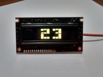
Ah, the pleasures of automation. I've received the first batch of stuffed boards from my manufacturer, and they are very pretty. I'm quite accomplished with a soldering iron, but I could not compete with the quality of these boards. Just the right amount of solder, exactly placed, and soldered through the plated hole with solder showing on top of the board -- a superb electrical connection.
Somehow in converting my drawings to Gerber, an error crept into the process on one of the four boards. I discovered it when I got them back from the board manufacturer, and the error was something I could not find in any of my drawings leading up to the Gerber, it somehow must have happened in the conversion and I didn't catch it. Anyway, I was anticipating an unsightly jumper wire on the board. Well, it's there, but not only is it not unsightly, I had to look and look to find it at all. They did totally awesome work in making it disappear. If you don't intentionally look closely for it, you'll never see it.
Tomorrow I will plug in some programmed chips and LDRs and check one out. If all goes well, then I'll start programming chips.
Last edited:
The PCB assembler found the error and corrected it before dispatch!
Brilliant service !!!!
Tell us who they are.
Brilliant service !!!!
Tell us who they are.
I think technology will have moved on long before any of these issues present themselves in any meaningful way.
The real issue with OLED displays is that there is an upconverting voltage regulator on the board that can send noise back down the power supply line to disrupt sensitive audio circuits. I've consulted with someone who has studied the issue and he is satisfied that by using separate regulators for the OLED and for the audio control circuitry, this noise does not reach the audio circuits. In my system, each board has its own regulator so there is very good separation of the OLED from the critical LDR control circuit. I cannot detect any issue with noise on the LDR control circuits.
Am I prescient, or what? A week after I said that, technology has already moved on -- there will be a slight delay in display availability while I test the possibility of automatically dimming the display in addition to moving the volume number around the screen after a few minutes of no control input. A dimmed display uses less power and produces less noise than a full brightness display. Dimming will be a good thing.
I got a PM from a gentleman who asked: can my system be used to build a balanced line preamp?
I don't know much about balanced line equipment, but if I understand the requirement correctly, one of my stereo unbalanced boards could be used as a single channel balanced control. Have I got that right?
Am I correct that the main requirement is for both sides of the balanced line be attenuated exactly the same at every attenuation level? If that's the case I think that two of my boards could be used to create a stereo balanced preamp.
Can someone who knows balanced technology confirm that for me?
No. And I'm not an expert, I get my information FROM the experts (Jung, Self, Whitlock etc).......... can my system be used to build a balanced line preamp?
.......... if I understand the requirement correctly, one of my stereo unbalanced boards could be used as a single channel balanced control. Have I got that right?
Am I correct that the main requirement is for both sides of the balanced line be attenuated exactly the same at every attenuation level?...................
The requirement for a balanced impedance connection is that the IMPEDANCE seen by the Source is identical, at least <1% error, but preferably <0.1% and that the impedance seen by the Receiver is identical.
If one of your LED/LDR attenuator were inserted into the relevant position of B.Putzeys balanced attenuator, then it would work since his circuit pre-processes and post-processes the input and output impedances to ensure the balance of connection impedances.
The signal levels on the Hot and Cold lines are unimportant, since the Receiver reads/measures the DIFFERENCE between the Hot and Cold lines and processes that difference.
Last edited:
Yes, it does...thank you.
That OLED display looks so cool that I think I would have to get one of those, too.
I thought I read somewhere that OLEDs have a limited life. Is there a way that the display could be turned off if not changing any of the functions?
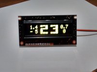
The OLED just got even better -- with improved readability across the room and display dimming.
The Volume number is now two rows high, and very readable from across the room. The milliamp display and the balance display remain one row high and everything can be displayed at once. The Calibration screen and the Balance adjust screen and the screen saver screen have not changed.
In addition, about 90 seconds after the last control input, the display will revert to 'screen saver' mode AND dim. With these two protective features in place it's going to be a long time before this display shows any degradation from burn in.
Here are images of the latest display configuration. Note that the milliamp values between channels is very different -- because the balance is shifted to the right (lower volume = higher current).
Attachments

Last edited:
The larger volume number is nice addition.
Looks like your kit keeps getting better and better.
Looks like your kit keeps getting better and better.
very interested.
i'm the sort of person who actually enjoys getting up and turning the volume up/down but TBH it stays pretty much at the same level for all my listening. so would it be possible to have only the LDR board without the display, remote etc.etc.
i only listen to one source through a headphone amp which has an on/off and volume as i like minimalistic stuff.
would like one before you decide to put everything in a box and then charge mega bucks 🙂
I've been relearning what I used to know about building websites, and now making some progress.
This website has not been released to search engines yet, so only people who know the URL can find it and look at it. I would welcome comments or suggestions at this point -- I'll happily incorporate good ideas right from the get-go.
Keep in mind, this is really a first cut.
This website has not been released to search engines yet, so only people who know the URL can find it and look at it. I would welcome comments or suggestions at this point -- I'll happily incorporate good ideas right from the get-go.
Keep in mind, this is really a first cut.
Hi Wapo54001,
Site looks pretty good for a first setup, adding the shopping cart will be the hardest thing perhaps.
Have you considered to use software specially designed for webshops? That will offer you the shopping cart, payment options etc. Examples are OsCommerce, OpenCart. They will make managing everything a lot simpler, including keeping track of orders, payments and shippings.
I am very interested in a set, but I must be honest to not expect the price to be so high. You have made without a doubt the best kit that is around, and thought of everything, even the things that were not discussed by the members here. If I read that the system only needs to be calibrated once in its lifetime, why is this whole calibration routine needed in the final boards? They could be factory calibrated and shipped without the extra options perhaps?
With kind regards,
That's neat, how what does the rotary encoder output?
It wouldn't be too hard to use a bluetooth module, and hook it up to my app.
(As long as I send the right commands).
It wouldn't be too hard to use a bluetooth module, and hook it up to my app.
(As long as I send the right commands).
Hi jslot,
With the recalibration feature, any disaster like a dc offset that 'burns' the ldrs, for example, can be rebuild with any problems - I love this feature.
One of the earlier ldr volume controls here suffered this very fate - never did get it back to original 'sound' whatever I tried.
The cost is relative to each of us - I think the mentioned price is actually the cost of parts and assembly with a negligible profit margin, if any, for these early modules - in comparison to a simple good quality $25 pot, it is more expensive but in comparison to my PassLabs preamp, for example, it's a pretty humble price.
All the best ...
Sorry, the above phrase
can be rebuild with any problems
would read a bit better as "can be rebuilt without any problems' (replace the ldr module and recalibrate the unit)
can be rebuild with any problems
would read a bit better as "can be rebuilt without any problems' (replace the ldr module and recalibrate the unit)
Hi Wapo54001,
Site looks pretty good for a first setup, adding the shopping cart will be the hardest thing perhaps.
Have you considered to use software specially designed for webshops? That will offer you the shopping cart, payment options etc. Examples are OsCommerce, OpenCart. They will make managing everything a lot simpler, including keeping track of orders, payments and shippings.
I am very interested in a set, but I must be honest to not expect the price to be so high. You have made without a doubt the best kit that is around, and thought of everything, even the things that were not discussed by the members here. If I read that the system only needs to be calibrated once in its lifetime, why is this whole calibration routine needed in the final boards? They could be factory calibrated and shipped without the extra options perhaps?
With kind regards,
Fine-tuning the website is ongoing, it'll probably never stop -- I'm an engineer who needs a manager to tell him when to stop, and I don't have a manager. 🙂
I am NOT saying the LDRs will never need calibration, I am saying that I myself have never had to recalibrate my LDRs after the first calibration. YMMV, and it probably will.
However, I do believe that my system has advantages over Lightspeed-type circuits that make mine more stable both in the short term and long term.
Short term stability is enhanced because I control LED current, not voltage, and LEDs are current-driven devices. Any voltage-control method is bound to be less effective because temperature changes at the LED junction affect the amount of current passing through the LED even if voltage is held constant. This changes brightness and that changes LDR resistance even if voltage is held steady.
Long term, my circuit will remain more stable because current through the LDRs is strictly limited to 10 milliamps or less, which is half of the device's published rating of 20~25 milliamps maximum. BTW, it has been recently suggested in another thread that PIC-controlled systems can damage LDRs by delivering excessive current to make unmatched LDRs match up, but the reverse is true -- I control the current down to the micro-amp level, and maximum current is never more than 10.005 milliamps, and almost always far, far less! Anyway, a 10 milliamp drive to a 20 milliamp-rated LED is not going to hurt, or even stress it.
As an aside, for folks who have an LDR preamp based on the voltage-controlled circuit with 100 ohm trimmer I've seen published in various threads, you might want to do the math. The LDR LED is rated at 25 milliamps at 2.5V drive, and that means with a 5V supply the trimmer must drop 2.5 volts. Dropping 2.5 volts through 100 ohms will deliver 25 milliamps which I believe is too much and, further, if you reduce the resistance of the 100 ohm trimmer to balance the channels as the instructions direct, the trimmer will now pass more than 25 milliamps at 2.5 volts and that seems to me to be a real no-no. This circuit should have something like a 125~150 ohm fixed resistor and a trimmer that is set to zero and then increased to balance channels. This approach will actually protect your LDRs. However, driving the LDRs conservatively in this circuit may not give you much attenuation, and probably that's why the max current is set so high, and this may be why LDRs have the reputation of changing over time.
In any case, I believe that because my circuit allows the LDRs to loaf along at 10ma maximum, there isn't much change in the LDR responses over time.
That's neat, how what does the rotary encoder output?
It wouldn't be too hard to use a bluetooth module, and hook it up to my app.
(As long as I send the right commands).
Rotary encoders send two sets of pulses, and the receiver must decode the pulse rate and which pulse occurs first, A or B. Or, something like that, I'm not an expert and it's complicated, I just made it work.
A separate circuit monitors a momentary switch which closes when you press in on the control knob, and that switches between Volume & Balance & Mute & sets which dataset is displayed on the OLED.
It would be very cool if you could make that work with Bluetooth!
That's neat, how what does the rotary encoder output?
It wouldn't be too hard to use a bluetooth module, and hook it up to my app.
(As long as I send the right commands).
If you can make your bluetooth receiver do pwm, you could output the pwm signal to the Volume and Balance potentiometer inputs of the main LDR board. Creating voltages of 0~5 volts will give you full control of attenuation and balance. Display won't work, though, it needs the RE board.
Well, I think u need to setup the bluetooth module to get an arduino to do the pwm for that controller. It is possible.
You wouldn't need a display, the settings can be displayed within the app.
You wouldn't need a display, the settings can be displayed within the app.
- Status
- Not open for further replies.
- Home
- Source & Line
- Analog Line Level
- A precision LED/LDR-based Attenuator