Thanks Walter,
Yeah, I'll keep my V1.0 board populated for a comparison even though it will be like comparing apples to oranges - still it will show just how different the 1541 can sound when implemented differently. Although it's always had a certain level of musical pizazz about it regardlessly.
Ryan
Yeah, I'll keep my V1.0 board populated for a comparison even though it will be like comparing apples to oranges - still it will show just how different the 1541 can sound when implemented differently. Although it's always had a certain level of musical pizazz about it regardlessly.
Ryan
Update
Prototype ordered!
Made a few amendments, and went over the schematics and pin outs a few more times this week just to make sure before I made the order. Although changes can and probably will be made before the final run. For the prototype I had to change the stripline thickness to suit the standard stackup the manufacturer offered to get correct impedance. Should be about 2 weeks or so till they arrive. Time to order some parts.

Ryan
Prototype ordered!
Made a few amendments, and went over the schematics and pin outs a few more times this week just to make sure before I made the order. Although changes can and probably will be made before the final run. For the prototype I had to change the stripline thickness to suit the standard stackup the manufacturer offered to get correct impedance. Should be about 2 weeks or so till they arrive. Time to order some parts.
Ryan
Attachments
hi Ryan, nice work. Can you post an updated schematic, and a BOM? I would like to order some parts.
Hi Luke,
Once I've tested the design and all is well, I'll finalise the schematics and BOM. The shunt regs are basically what I posted earlier though. Recently I added the 2220 pads for the 22uF films and 1812 pads for the 10uF films (Rubycon ST). Also added the inductor with DC resistance of about 9 ohms, 3.3mH in place of the current sensing resistor in the CCS.
Cheers.
I've subscribed to this thread and will be eagerly awaiting the board official release. Have fair few 1541's that need to find home. Once they settle-in and unpack, I am pretty sure there will be people I know who'll appreciate the sound (paired with WaveIO...maybe...)
Nick
Nick
Hi Nick,
WaveIO is definitely a good option. I would recommend getting your hands on Ian Canada's I2S to PCM converter if you can. Running the 1541 in simultaneous mode only improves things.
Cheers
WaveIO is definitely a good option. I would recommend getting your hands on Ian Canada's I2S to PCM converter if you can. Running the 1541 in simultaneous mode only improves things.
Cheers
Pin pitch
Hi Guys,
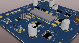
Most of my parts have arrived, PCB prototype should arrive Tuesday.
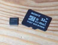
Just wanted to attach a photo of the 16TSSOP package that is going to be used for the reclocker; to make everyone aware of what they are up against. Smaller packages offer better performance due to a smaller current loop.
There are a few different techniques to soldering packages with this pin pitch, here is a clip of drag soldering.
Plenty of other videos out there with varying techniques. Definitely doable for your average diyer.
Cheers.
Hi Guys,
Most of my parts have arrived, PCB prototype should arrive Tuesday.
Just wanted to attach a photo of the 16TSSOP package that is going to be used for the reclocker; to make everyone aware of what they are up against. Smaller packages offer better performance due to a smaller current loop.
There are a few different techniques to soldering packages with this pin pitch, here is a clip of drag soldering.
Plenty of other videos out there with varying techniques. Definitely doable for your average diyer.
Cheers.
Attachments
Last edited:
Nice video. I always find the correct chip positioning to be hardest. Once positioned and few of its pins soldered, the remaining process pretty much should focus on keeping the chip flat.
Regards,
Nick
Regards,
Nick
Good advice, thanks Nick.
I usually use heaps of flux, pointy tweezers, and definitely no caffeine before SMD soldering.
A solder well tip or a chisel soldering tip will help when drag soldering.
Im sure everyone will figure it out.
Just thought i'd bring it to attention.
🙂
Ryan
I usually use heaps of flux, pointy tweezers, and definitely no caffeine before SMD soldering.
A solder well tip or a chisel soldering tip will help when drag soldering.
Im sure everyone will figure it out.
Just thought i'd bring it to attention.
🙂
Ryan
Looks good 🙂
maybe if your a surgeon. Ryan, is there enough space between components to get an iron in when it starts getting populated? I am nervous about building something this tight with just an iron. What about built modules, is this cost prohibitive or possible?
maybe if your a surgeon. Ryan, is there enough space between components to get an iron in when it starts getting populated? I am nervous about building something this tight with just an iron. What about built modules, is this cost prohibitive or possible?
Shouldn't be too much of a problem if you use solderpaste 🙂
Hi Luke, Mayday.
Luke, I understand your concern.
During the build process of the prototype i'll take note of things that need adjusting on the pcb and change for the final run - this may include space constraints and footprint sizes. No need to panic yet, this is just the prototype. Ill try to make it as easy as I can for diyers without compromising performance too much.
Mayday is right, solder paste will be a good option.
Built modules are off the table at the moment, I just haven't got the time or resources, unfortunately.
Ryan
- Home
- Source & Line
- Digital Line Level
- TDA1541A Diy Pcb - "Distinction-1541 v2"