So man up and accept you stumbled upon something that was already well known and we can move on from there.
Well this is not quite the case. The already known cases don't address Joe's two main claims:
1. Improvement is gained by a very particular FR roll off.
2. Similar improvement can be gained in the 8 scenario given at the beggining of this thread.
Prior art mostly refer to something similar to "scenario 6". Of course prior art don't make any claim about special sound being gained from a particular frequency response. Nor does it allow to link together the 8 scenario.
What is hard to believe is that there is really a common element to all 8 scenario. It is easier to believe that each scenario in particular could have audible effects.
Last edited:
Joe, I have an old Sony player, the output stage of which is attached... and I was wondering about trying your 'Scenario 2' mod. Any thoughts on suitable component values which I've marked as Rx and Cx in the second diagram. The DAC is a CXD2552Q.
My intention would be to make some 'before' and 'after' files of the player (which I could post here) and see what sonic differences were/were not apparent.
My intention would be to make some 'before' and 'after' files of the player (which I could post here) and see what sonic differences were/were not apparent.
Attachments
There is actually the whole thing about this subject in discussion here. This cap and filtering approach it brig a new dimension for the reproduced sound, in conjunction with DACs processing.
Indeed this filtering method (differential filter) it was used before as the few presented here materials shows, and is known for a while. As I could see/understand, this filtering it was applied before to an quite different I/V approach (a passive one), followed by the final buffer.
The most common way to use this filter in Joe`s approach is placing the cap on DAC`s +/- outputs, before an active I/V circuit (opamp). Well, there are some other configurations too. This it may looks to me as an innovation or modification of the classical (used before) approach.
I used it like this (directly on the DAC chip outputs, and before the active I/V converter), and I noticed improvements for the outputted sound. It is obvious that something positive it happen for the involved signal. In which way and how, it still to be clarified/founded...
Last edited:
.... It is obvious that something positive it happen for the involved signal
the improved stereo effect and localization of sound images; silk, soft high-frequency???
the improved stereo effect and localization of sound images; silk, soft high-frequency???
For my own I think this it may happen in the HF domain somehow. But a obvious effect it is also in the low range of spectre.
I specially noticed this through my experiences (not only about this " cap effect"): any hardware improvements in HF domain of the involved circuits, it had always an positive impact for the lower range of the spectre too.
Sometimes, improving the circuits for the HF range was not so noticeable in outputted high end spectre of the sound, but more in the lower end...
 thread opened...please stick to technical comments and refrain from personal stuff, shoot the message, not the messenger....
I've been having a look at this mod with a view to seeing how it pans out on a voltage output dac. Also, there are a couple of ideas I want to try following on from this.
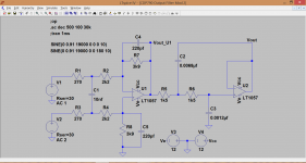
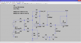
State of play so far. I modded the output stage (see post #702 for original layout) so that it now looks like this. Taking actual measurements while experimenting allowed to me deduce that the DAC output impedance is around 30 ohms. Adding that figure to the simulation gives the following response. I was surprised when I studied the circuit that the final opamp stage isn't a low pass filter, it has a slight hf rise to the response. The output of the first opamp is also shown so that you can see how the final stage corrects the response.
How does it sound... well truth be told I haven't seriously compared the two as yet.
Some thoughts along the way as they occured...
1/ I did add a super cap to the main DAC supply, a 0.22F as it was all I had. The DAC in the Sony has quite a few rail feeds, and one is via a 10 ohm and extra decoupling. A practical thought occured... could adding a super cap cause a 'race hazard' situation where the cap actually slows the rate of rise of the rail enough to cause the various chips not to initially recognise and talk to each other but to lock up instead. In my case that hasn't happend but it is something to bear in mind.
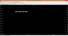
2/ In my example here, the 100 ohms + 10nf cause a -/+2ma current draw from the DAC at full output and measured at 19kHz. Could that non linear (non linear as in its now a frequency dependent loading) cause any distortion effects that could be attributed to the final sound (which I haven't listened to intently as yet).
3/ To be continued... I have made files of the player in its original state and with this mod as shown. What I want to do next is alter the component values somewhat while still keeping the overall gain similar to original spec. I'll post details of that later if things work out.
State of play so far. I modded the output stage (see post #702 for original layout) so that it now looks like this. Taking actual measurements while experimenting allowed to me deduce that the DAC output impedance is around 30 ohms. Adding that figure to the simulation gives the following response. I was surprised when I studied the circuit that the final opamp stage isn't a low pass filter, it has a slight hf rise to the response. The output of the first opamp is also shown so that you can see how the final stage corrects the response.
How does it sound... well truth be told I haven't seriously compared the two as yet.
Some thoughts along the way as they occured...
1/ I did add a super cap to the main DAC supply, a 0.22F as it was all I had. The DAC in the Sony has quite a few rail feeds, and one is via a 10 ohm and extra decoupling. A practical thought occured... could adding a super cap cause a 'race hazard' situation where the cap actually slows the rate of rise of the rail enough to cause the various chips not to initially recognise and talk to each other but to lock up instead. In my case that hasn't happend but it is something to bear in mind.
2/ In my example here, the 100 ohms + 10nf cause a -/+2ma current draw from the DAC at full output and measured at 19kHz. Could that non linear (non linear as in its now a frequency dependent loading) cause any distortion effects that could be attributed to the final sound (which I haven't listened to intently as yet).
3/ To be continued... I have made files of the player in its original state and with this mod as shown. What I want to do next is alter the component values somewhat while still keeping the overall gain similar to original spec. I'll post details of that later if things work out.
Attachments
I've been having a look at this mod with a view to seeing how it pans out on a voltage output dac. Also, there are a couple of ideas I want to try following on from this.
State of play so far...
It's late here adn as usual, when many of you awake I am getting ready for sleep.
But just a quick comment or two.
RX_a and RX-b are critical, yes they can create unacceptable load, the ideal could be a fair bit higher. With hindsight, with the Zobel network an indication, that it may need to be 470R and I need to edit the example, I think in Post #2.
Your point re AC current drawn @ 19KHz, that bears thinking upon, that changes things.
In that case, I can see 470R and 15nF doing the job. That is near 1K to 1K5 as used in the Zobel plus some DCR in the transformer, since txs is what I have preferred and have more experience txs. So this needs refining and a good opportunity.
Yes, I can now see that retaining those 2 x 9K1 makes sense because of the DC current drawn.
I would do without that C1 470pF. Our new cap as a pole should take place of that, just at lower frequency.
So, before I nod off, this is where even I am getting to think about what you are feeding back to me, as I may in fact made a miscalculation. It needs nailed down.
We are not there yet to have a listen - getting there. Use 470R and tweak cap to get the response. Then it should be worth a listen.
Cheers, Joe
I'm running out of time to (afternoon here) but I've just had a quick listen over two different tracks and I've ended up preferring the modded player for one track, but not for the other. I'll put the files up a bit later so anyone can listen.
I'll study what you have written later... out of time too.
I'll study what you have written later... out of time too.
So here are the files for the modification as per post #708. Four tracks in total, two different pieces of music. Modified vs un-unmodified for each set. As I mentioned above, I preferred modded for one, unmodded for the other.
For anyone not familiar with Dropbox you do not need to sign up to get the files. Just close the registration invite window and then download the zipped folder of files. Folder size is 74Mb.
Modification 1
For anyone not familiar with Dropbox you do not need to sign up to get the files. Just close the registration invite window and then download the zipped folder of files. Folder size is 74Mb.
Modification 1
Attachments

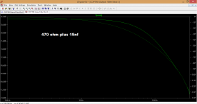
In that case, I can see 470R and 15nF doing the job.
I tried simulating those values but found them not to be workable as there is far to much un-correctable hf roll off. 6n8 or 5n6 could possibly work, with 5n6 giving a slightly rising response... see text below.

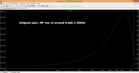
Now this leads on to another curious aspect of this players output stage. In its un-modified form the circuit has a slightly rising hf characteristic. It looks dramatic but in reality amounts to just 0.4db or so at 20kHz.

Using 5.6nf and 470 ohms gives a similar response to standard spec. Note how the feedback resistors need recalculating to keep the gain of the signal path similar to the un-modified player.

Response of 5n6 and 470 ohm.

Finally, this is a version I came up with that seems to give a reasonably flat response.

Response. Although it looks (and does) show a falling HF response you need to look at the scale to see how little the deviation is.

Attachments

Yes, it was late, woke up in the morning and did a mental calculation and 15nF is definitely too much. I ran it quickly in SoundEasy and -2dB @20KHz was near 6nF - so 5.6nF should be OK.
I admit, I have 'nailed' the values fairly well for "current" DACs (3R3 & 1uF), but I now recognise not so for "voltage" DACs.
There is plus in this, that using 470R and maybe even higher up to 680R, that the DAC output impedance is now only a few percent of that and in the end that is now largely taken out of the calculation, a good thing. It should mean that we can end up with standard or recommended starting values for "voltage" as well. I like that and makes it easier for others coming after us. I can see 470R and 5n6 as that possible combination.
Why I have come up short here? It comes back to the fact that I have preferred using 1:1 transformers (even the cheap Vigortronics VTX-102-007 works so well and really musical) which takes out all opamps and their attendant power supply - this is admittedly also because I prefer getting opamps out when I can, not something I impose on others.
Something else comes to mind. One of the Burson Conductor Preamp/DAC fitted with Sabre DAC and into passive I/V to ground, 1K I seem to recall. I ended up around 5nF there, across the resistors to ground, the two phases both seeing the cap. I checked that out in SoundEasy too and with the single phase the DAC Z was 781R and the 1K to ground, they are effectively in parallel and = 438R. Same ballpark.
Re: Installing and using LTspice. From beginner to advanced - something I will be checking out at a later time, lot on plate right now.
Cheers, Joe
Mooly, did you try experimentally determining the frequency response? That seems like a logical first step, but of course, there's no reference measurement from Joe to compare it to... at least you can see if there's any gross errors introduced by the "mod."
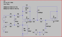
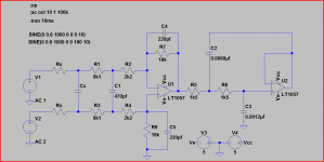
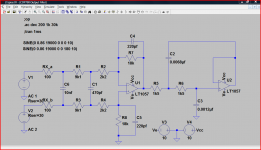
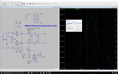
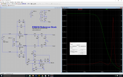
Back alive. For the life of me, I could not get the LM4562 to play nice, so these sims are made using LT1115, which should play fairly well in this situ, and means that the .asc's provided don't need any non-stock libraries.
These are all based off of the recommended differential I/V circuit from the ES9018 datasheet. For Joe's mod, I placed the 3r3 and 1uF capacitor up front, and bypassed the 1k output resistors with 12nF caps, per his recommendations.
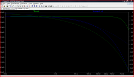
ES9018_Ref_Stock shows the linear gain and output referred noise of the stock circuit with its stock values.
ES9018_Ref_Joe shows the linear gain and output referred noise of Joe's modifications, where we can see the transimpedance noise gain in full effect, as seen in Scott's post above.
ES9018_Ref_Joe_Gain shows that the circuit is indeed 2 dB down at 20 kHz.
Feel free to ask any questions. Just don't ask me to use the LM4562 model in LTSpice. 😀
These are all based off of the recommended differential I/V circuit from the ES9018 datasheet. For Joe's mod, I placed the 3r3 and 1uF capacitor up front, and bypassed the 1k output resistors with 12nF caps, per his recommendations.
ES9018_Ref_Stock shows the linear gain and output referred noise of the stock circuit with its stock values.
ES9018_Ref_Joe shows the linear gain and output referred noise of Joe's modifications, where we can see the transimpedance noise gain in full effect, as seen in Scott's post above.
ES9018_Ref_Joe_Gain shows that the circuit is indeed 2 dB down at 20 kHz.
Feel free to ask any questions. Just don't ask me to use the LM4562 model in LTSpice. 😀
Attachments

Back alive. For the life of me, I could not get the LM4562 to play nice, so these sims are made using LT1115, which should play fairly well in this situ, and means that the .asc's provided don't need any non-stock libraries.
These are all based off of the recommended differential I/V circuit from the ES9018 datasheet. For Joe's mod, I placed the 3r3 and 1uF capacitor up front, and bypassed the 1k output resistors with 12nF caps, per his recommendations.
ES9018_Ref_Stock shows the linear gain and output referred noise of the stock circuit with its stock values.
ES9018_Ref_Joe shows the linear gain and output referred noise of Joe's modifications, where we can see the transimpedance noise gain in full effect, as seen in Scott's post above.
ES9018_Ref_Joe_Gain shows that the circuit is indeed 2 dB down at 20 kHz.
Feel free to ask any questions. Just don't ask me to use the LM4562 model in LTSpice. 😀
The noise with the 4562 is about 2.7X with all else equal which seems about right.
Yup. I should also mention that the LT1115 is probably not a good idea from a stability perspective, even if it doesn't blow up in sims with this circuit (I checked with some transients). Mostly picked it because it has similar GBW, is a BJT input with decent input bias compensation, and has similar noise characteristics.
And, most importantly, native library support.
And, most importantly, native library support.
OK we're getting somewhere, if the claims are around a critical -1 to -2 dB roll-off with a sudden "snap-in" at a certain point then I would doubt simulation or measurement will show any sudden dramatic change in harmonics or out of band energy just the simple roll-off change. In other words I doubt measurements will uncover anything worth blaming, this leaves us with listening tests at .5dB or so increments.
As mentioned before the digital roll-off in small increments is trivial to achieve with a single biquad filter if anyone just wants to listen to that without the analog modification.
I consider a 50-100X increase in noise potentially a gross error. It might in fact with many op-amps not be particularly audible.
As mentioned before the digital roll-off in small increments is trivial to achieve with a single biquad filter if anyone just wants to listen to that without the analog modification.
at least you can see if there's any gross errors introduced by the "mod."
I consider a 50-100X increase in noise potentially a gross error. It might in fact with many op-amps not be particularly audible.
Last edited:
"Rolling" opamps at the transimpedance stage, one also needs to pay close attention to gain peaking--the feedback capacitor must be appropriately adjusted as well.
"Rolling" opamps at the transimpedance stage, one also needs to pay close attention to gain peaking--the feedback capacitor must be appropriately adjusted as well.
You learn well grasshopper. 😉
- Status
- Not open for further replies.
- Home
- Source & Line
- Digital Source
- Practical Implementations of Alternative Post-DAC Filtering