Hi ljm_ljm and others,
What would you say about this L150W?:
Assemble Dual Channel L150W FET Power Amplifier Board IRFP240 6 with Radiator | eBay
Personally I like its design, the look and the fact it isn't made on complementary MOSFET pairs, just 6xIRF240 per channel, much resembles my old NAD208.
Any possible downsides?
What about this other. Is this also your design?
RGDS
PEMO

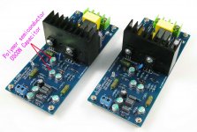
B: yes. It is my product.
Its capacitance has more high withstand voltage 75 v 220 uf
So it can use 50 v transformer.
If your low voltage transformer, recommend 63 v2200uf capacitance 8 only that one.
Because it has the better rectifier, MUR860G
Hi ljm_ljm and others,
What would you say about this L150W?:
Assemble Dual Channel L150W FET Power Amplifier Board IRFP240 6 with Radiator | eBay
Personally I like its design, the look and the fact it isn't made on complementary MOSFET pairs, just 6xIRF240 per channel, much resembles my old NAD208.
Any possible downsides?
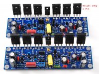
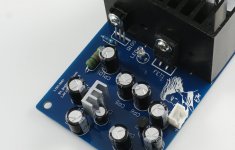
This is my design in 2013. My name is L150W.
It is to use a total of 6 IRFP250 power tube, perhaps the businessman is not very professional, the model made a mistake.
I recommend more relatively L15. It USES IRFP240 IRFP9240 six altogether.
From my test conclusion, the N + P mode is better than all use N field-effect tube performance.
Attachments
Although I haven't updated product development.
But I have been constantly improve it.
The same model, different versions, and I think a good amplifier is in progress.
Rather than just for the sake of profit margins.
I hope to get a better sound, not the appearance of more beautiful and lower prices.
Constantly updated.
But I have been constantly improve it.
The same model, different versions, and I think a good amplifier is in progress.
Rather than just for the sake of profit margins.
I hope to get a better sound, not the appearance of more beautiful and lower prices.
Constantly updated.
Attachments
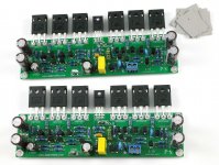
ljm, if you update the board, why not add more room for larger power capacitors ?
220µF is low. Its is a weakness of the boards. We can tweak for larger capacitors, but they are larger and require more space.
Just some traces to move on the board.
220µF is low. Its is a weakness of the boards. We can tweak for larger capacitors, but they are larger and require more space.
Just some traces to move on the board.
Although I haven't updated product development.
But I have been constantly improve it.
The same model, different versions, and I think a good amplifier is in progress.
Rather than just for the sake of profit margins.
I hope to get a better sound, not the appearance of more beautiful and lower prices.
Constantly updated.
Appreciated for intent, though it would be nice if it worked. Which mine doesn't, and in the absence of any documentation or support, it is $5 of parts that I paid $20 for.
ljm, if you update the board, why not add more room for larger power capacitors ?
220µF is low. Its is a weakness of the boards. We can tweak for larger capacitors, but they are larger and require more space.
Just some traces to move on the board.
I try to 100 uf 220 uf didn't see the difference on the instrument.
Because I use 5600 uf in circuit board outside * 4 capacitance.
12000 UF *2 Is parallel with 220 uf in principle
You can increase the 2, 10000 UF capacitor. Just like the ARC DSI225. It may use up more than 50000 UF capacitance.
I will remember your advice. May increase a little size. In the future.
Like right now I've been using OSCON 25 33UF instead of aluminum electrolytic capacitor ,The original is 22 uf
PCB single-sided effect will be better, less distortion. From the test conclusion.
Anyone can measure
Last edited:
Appreciated for intent, though it would be nice if it worked. Which mine doesn't, and in the absence of any documentation or support, it is $5 of parts that I paid $20 for.
I'm sorry. L15D easy to install. As long as know capacitance and resistance.
And I also Installation of finished product. Prices are basically the same.
If you have any installation difficulties can contact with me.
Hi do you have a webshop ? Where to look through and buy LJM products ?
Aliexpress.com : Acquista L15d top digital amplificatore irs2092 irfi4019h (iraudamp7s) stereo prodotto finito da Fornitori amplificatore di karaoke affidabili su LJM AUDIO DIY
This you can refer to, such as data, images.
I don't know much about the international mail business, so you can put it as a reference for research.
There may be many in the sales agent of international business, or they have no update photos.
is it possible to run your L7 circuit using two (or even three) separate power supplies, one feeding just the output pair, one feeding the rest of the circuit. Another feeding the input would be even better, but what voltage would I use for the input only?
I want to build four of your L7 circuits, and I have eight of your power supplies (the ones with 4x2200uF caps per rail).
Thanks
I want to build four of your L7 circuits, and I have eight of your power supplies (the ones with 4x2200uF caps per rail).
Thanks
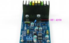
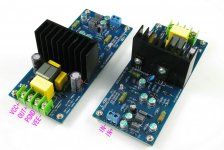
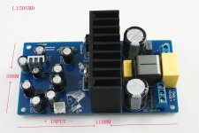
IRS2092 IRFI4019 L15DSMD AMP BY LJM
It is a SMD version L15D model.
The same structure.
By IRS2092S IRFI4019H composition.
It is a MINI version, the position of the element is similar to IRAUDAMP7S.
It suggested that + - 40 v to + 60 v voltage
Recommend + - 50 v voltage.
Can obtain 125 8 r w, 125 w 4 the output power.
Details about the test and can reference IRAUDAMP7S data.
Attachments
is it possible to run your L7 circuit using two (or even three) separate power supplies, one feeding just the output pair, one feeding the rest of the circuit. Another feeding the input would be even better, but what voltage would I use for the input only?
I want to build four of your L7 circuits, and I have eight of your power supplies (the ones with 4x2200uF caps per rail).
Thanks
Sorry I didn't look too understand what you mean.
A transformer, corresponding to use a power board 8 * 2200 uf.
Can connect many about. Unlimited number.
I mean this. I want to supply +/-50 volts to just the output FET's, and +/-42 volts to the rest of the circuit. I already have all the power supplies and transformers:
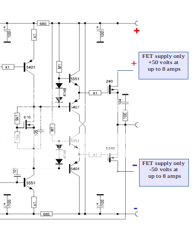
And if possible, a low voltage to just the input LTP. Thanks for reply.

And if possible, a low voltage to just the input LTP. Thanks for reply.
Of course you can. Polymer semiconductor solid capacitors extremely well.
25V22UF or 33UF
Hi, I was just about to order some OS-CON 25V caps when I noticed that the ones they are supposed to replace are rated at 65V. The PSU is supplying 52V DC to my L15D PRO boards. Will a 25V cap work here ?
Thank's for your feedback.
Greetings !🙂
Hi, I was just about to order some OS-CON 25V caps when I noticed that the ones they are supposed to replace are rated at 65V. The PSU is supplying 52V DC to my L15D PRO boards. Will a 25V cap work here ?
Thank's for your feedback.
Greetings !🙂
bump 😉
Just search on Ebay for L15DSMD
Assembled L15DSMD 250W Digital Mono Amplifier Board IRS2092 IRFI4019H | eBay
Assembled L15DSMD 250W Digital Mono Amplifier Board IRS2092 IRFI4019H | eBay
- Home
- Vendor's Bazaar
- LJM Audio