Hi Ivo,
I have one more question for you regarding the “Frequency Domain 2Ch Averaging” button when left unchecked; does it average in the time domain? Also, it is my understanding that by averaging several responses in the time domain, you can reduce the ambient room noise when making acoustic impulse measurements, but do you get similar benefits from averaging in the frequency domain?
Peter
Freqency domain 2Ch averaging uses different noise signal for every sequence. Averaging is in frequency domain. It reduces external noise (like time domain averaging) and additionally reduces stationary disturbances and nonlinear distortions - as different noise sequences randomize stationary disturbances and distortion. Only bad side is that it needs more time than time domain averaging.
Ivo
Why should that bias occur? I don't see any evidence of it when comparing 2 sweep measurements of -18 dBFS input vs -66 dBFS input on a 16-bit soundcard loopback.Problem with swept sine becomes aparent with low level signals. For good results we need to satisfiy at least 12 bit resolution. If you have lower level of acquired signal the result become biased.
Attachments
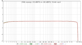
Why should that bias occur? I don't see any evidence of it when comparing 2 sweep measurements of -18 dBFS input vs -66 dBFS input on a 16-bit soundcard loopback.
Hi John,
glad to hear you.
I am looking at your measurement data and I see that at low frequencies there is at least 0.1 dB difference. Now if we suppose that some "error signal" has made that difference we can calculate that error signal is -36dB below measured level (10^(0.1/20) == 1.0158 -> 20*log10(1.0158-1) = -36dB). I've concluded that your measurements (with low level signal) at low frequencies had dynamic range of 36dB. The question is: will that difference be the same if we repeat the measurement. My experiments have shown that random noise is more stable than swept sine and that they give less variance with very low level signals.
Why?
The answer lies in analysis on how error signal (random or impulsive noise ) is transformed in cross-correlation (cross-spectrum) based processing. The noise or MLS signals used in ARTA have random phase properties which "randomize error" and distribute it equally over all frequencies. That is why averaging helps to reduce this kind of errors on all frequencies.
Now if we works with swept sine we get excellent results without averaging as it has largest crest factor, but when we measure low level swept sine response corrupted with noise, especially impulsive noise, crosscorelation processing does not distribute error (noise) equally over all frequencies, as swept sine has no random phase property. Spectrum of error signal is in most cases unpredictable and averaging does not help as is the case with random phase excitation signal.
This behavior of swept sine suggest that it is better to use random noise excitation with large number of averaging if we expect to measure very low level measured system output.
If you use my program LIMP you will see that I do not use swept sine for the loudspeaker impedance measurement, although I had lot request for that.
Simply, in impedance measurement loudspeaker acts as microphone and very often generate lot of impulsive noise. I have found that swept sine very often gives false results, while random noise, and especially stepped sine excitation gives predictable measurement variance.
Best,
Ivo
Hi John,
Thanks for joining in on this issue. Have you tried to duplicate the test I made in my post #395 showing the noise floor of my system with the measuring input shorted? The results I got are shown in Fig.4. BTW, I ran this test with the reference channel at –3dBFS.
Do you have any idea as to the cause of my problem if different from Ivo’s?
Peter
Thanks Ivo. The variation was a bit smaller (zoomed in below, with two measurements at -66 dB FS), S/N for the extracted IR on that -66 dB FS sweep is about 60 dB, but understand your point. The variation on PLB's post looked very large, but this loopback test has no impulsive noise of course so perhaps that is an important factor.

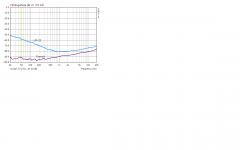
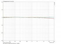
Hi Peter, it isn't especially meaningful to do a sweep measurement on a shorted input, you may as well just use the RTA to look at the noise floor. Here is a comparison of a 256k sweep (red) vs 85 averages of a 128k FFT 1/48th octave RTA plot (green) on the same soundcard I used for the sweep level comparison, but with the input shorted.

For your speaker measurements perhaps check that the IR window settings are appropriate, if the window is too short and/or not tapered you can get a lot of variation and ripple at low frequency.
Hi Peter, it isn't especially meaningful to do a sweep measurement on a shorted input, you may as well just use the RTA to look at the noise floor. Here is a comparison of a 256k sweep (red) vs 85 averages of a 128k FFT 1/48th octave RTA plot (green) on the same soundcard I used for the sweep level comparison, but with the input shorted.
For your speaker measurements perhaps check that the IR window settings are appropriate, if the window is too short and/or not tapered you can get a lot of variation and ripple at low frequency.
Peter, one thought about your LF measurement oddity: were the sweep measurements made in dual channel mode? If so, try single channel mode.
REW and ARTA swept sine resolution
Hi,
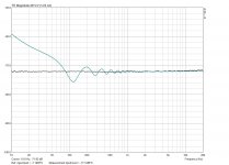
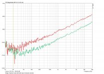
I have made swept-sine FR "noise floor" measurement for two sound cards : Steinberg UR22 and M-audio Transit USB, with ARTA and REW (see attachments). Both programs shows the same behavior: Transit has more or less similar level at all low frequencies, while UR22 has severe rise of noise floor toward low frequencies (30dB rise).
As I said in previous post we expect that swept sine measurement will be recorded with high dynamics, especially if sound card exhibit behavior like UR 22, and theoretically, I repeat, as problem with swept sine signal is that it needs high resolution in digital domain for correlation analysis. Farina suggests 12 bit resolution for good results, so in measurements it would be nice to keep peak of swept sine response in the range -30dBFS.
Random noise has better behavior with low level signal and by using averaging the noise floor can be additionally reduced.
Ivo
Hi,
I have made swept-sine FR "noise floor" measurement for two sound cards : Steinberg UR22 and M-audio Transit USB, with ARTA and REW (see attachments). Both programs shows the same behavior: Transit has more or less similar level at all low frequencies, while UR22 has severe rise of noise floor toward low frequencies (30dB rise).
As I said in previous post we expect that swept sine measurement will be recorded with high dynamics, especially if sound card exhibit behavior like UR 22, and theoretically, I repeat, as problem with swept sine signal is that it needs high resolution in digital domain for correlation analysis. Farina suggests 12 bit resolution for good results, so in measurements it would be nice to keep peak of swept sine response in the range -30dBFS.
Random noise has better behavior with low level signal and by using averaging the noise floor can be additionally reduced.
Ivo
Attachments
Hi John,
I think I may have unwittingly confused you with my shorting out the sound cards measuring input. I wasn’t really interested in the sound cards noise floor per se, I did it to simulate low level acquisition/post-processing behaviour between the PN and Swept sine conditions.
As for the widowing, In Fig.1, you will see a yellow line at the bottom of the graph on the LHS. This line stops at approx. 220Hz and represents the reciprocal of the gated time period. I normally set the start cursor at the first data point prior to the main impulse that is closest to 0Volts. I then gate the response just at the beginning of the first reflection with a Blackman4 window, which I think is a half window.
Like you, I have also found that small changes in the location of the gates can make an observable difference in the FR, however, when confronted with a low level Swept sine response, it becomes very difficult to set the start cursor anywhere in the time of flight area, because it is biased off of zero volts (even at t=0) by a significant amount. As a result of this it becomes just as difficult to set the gate before the first reflection, because the windowing function will always set the data to 0volts at the end of the gate period, which will not match the voltage at the start cursor!
It is for this reason that I think Holme Impulse uses a high pass window function at the beginning of the impulse to set the data to 0volts.
As for making single channel measurements, ARTA does not have Swept sine in single channel mode, so all of the measurements were made using 2channels.
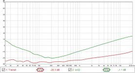
I have made two more measurements that may be interesting to you and Ivo. Both measurements where made at about –72dBFS (approx 12Bits below MSB). Fig.5 shows the FR when the Ref. channel is set to –7dBFS. Fig.6 shows the FR when the Ref. channel = the measurement channel.
In both fig’s, the green curve is the Swept sine.
As you can see, when the two channels are at the same level, Swept sine appears to work very well, but when the reference input is close to FS, the PN clearly wins out.
The more I find out about ARTA the more impressed I am with it.
Peter
I think I may have unwittingly confused you with my shorting out the sound cards measuring input. I wasn’t really interested in the sound cards noise floor per se, I did it to simulate low level acquisition/post-processing behaviour between the PN and Swept sine conditions.
As for the widowing, In Fig.1, you will see a yellow line at the bottom of the graph on the LHS. This line stops at approx. 220Hz and represents the reciprocal of the gated time period. I normally set the start cursor at the first data point prior to the main impulse that is closest to 0Volts. I then gate the response just at the beginning of the first reflection with a Blackman4 window, which I think is a half window.
Like you, I have also found that small changes in the location of the gates can make an observable difference in the FR, however, when confronted with a low level Swept sine response, it becomes very difficult to set the start cursor anywhere in the time of flight area, because it is biased off of zero volts (even at t=0) by a significant amount. As a result of this it becomes just as difficult to set the gate before the first reflection, because the windowing function will always set the data to 0volts at the end of the gate period, which will not match the voltage at the start cursor!
It is for this reason that I think Holme Impulse uses a high pass window function at the beginning of the impulse to set the data to 0volts.
As for making single channel measurements, ARTA does not have Swept sine in single channel mode, so all of the measurements were made using 2channels.
I have made two more measurements that may be interesting to you and Ivo. Both measurements where made at about –72dBFS (approx 12Bits below MSB). Fig.5 shows the FR when the Ref. channel is set to –7dBFS. Fig.6 shows the FR when the Ref. channel = the measurement channel.
In both fig’s, the green curve is the Swept sine.
As you can see, when the two channels are at the same level, Swept sine appears to work very well, but when the reference input is close to FS, the PN clearly wins out.
The more I find out about ARTA the more impressed I am with it.
Peter
Attachments
As for making single channel measurements, ARTA does not have Swept sine in single channel mode, so all of the measurements were made using 2channels.
Peter
Peter,
Please look at swept sine measurement dialog. You will find check box named "Dual channel measurement mode". If you do not check it the measurement will be in single channel mode; You will loose delay information and peak of impulse response will be set close to reference position 300.
If you want simultaneous measurements of IR and distortion you should check the box "Center the peak of impulse response". It is always done in single channel mode.
.-.
I am glad that you have experimentally confirmed my measurement recommendations.
Ivo
Hi Ivo,
"Please look at swept sine measurement dialog. You will find check box named "Dual channel measurement mode". If you do not check it the measurement will be in single channel mode"
Thanks for the heads up. I guess you realized that I was looking in the Fr1/Gen dialog. If I have time tomorrow, I'll try to run a low level FR using single channel mode. 🙂
Peter
Mine isn't the only UR22 that does that then. I thought it was broken, perhaps it is just very badly designed - on mine there are random input level fluctuations up to -50 dB FS on both channels with shorted inputs. 24 bits and only 8 of them useful.UR22 has severe rise of noise floor toward low frequencies (30dB rise)
The problem with UR22 (as well Scarlett 2i2) is converter digital antialiasing filter and bad driver.
I have found solution for driver problem but I can't change AD converter.
The question was shall I remove these souncards (as well some other) from my recommended list. I did not done that, as they can still can be usefull if user knows how and when to use swept sine and random noise.
Ivo
I have found solution for driver problem but I can't change AD converter.
The question was shall I remove these souncards (as well some other) from my recommended list. I did not done that, as they can still can be usefull if user knows how and when to use swept sine and random noise.
Ivo
This thread also seems relevant for UR22: www.steinberg.net • View topic - UR22 Low freq. noise due to grounding design DIY solution - pointing the finger at the grounding arrangement for the USB supply connections.
This thread also seems relevant for UR22: www.steinberg.net • View topic - UR22 Low freq. noise due to grounding design DIY solution - pointing the finger at the grounding arrangement for the USB supply connections.
This is bad designed product, I agree.
We always have design problem if we want cheap interfaces. I have been testing interfaces for decade, and cheap products are becoming worse and worse.
Here are general findings:
1) Bad Realtek codecs have replaced very good Analog Devices codecs on almost all computer motherboards
2) TI series of cheap codecs, found in many usb audio (diy) project, are just worse than motherboard codecs.
3) Music recording sound cards follows the same price / quality degradation (example is UR22 or Scarlett 2i2).
4) Good sound cards are expensive.
5) Some expensive cards use cheap AD/DA converters or op-amps, or have driver stability problems and testing is welcomed before buying.
6) Many music recording sound card have high noise at low frequencies, simply their authors think that LF noise will not be heard. For instance Egosys U24 has the same codec as M-Audio Transit but high noise on line output, as it uses cheap headphone driver amplifier on line output.
All these findings were reason why I've recommended testing sound card's
1) THD 2) FR 3) dynamic range over all frequency in spectrum and FR analysis.
Ivo
Hi Ivo,
Re, PN v SS measurement methods. I unchecked the 2 channel button as you suggested in your earlier post (to make single channel measurements) and shorted both input channels, with results shown in Fig.7 attached.
As you can see, the green curve = SS, now matches the PN response shown in Fig.4 in my first post, which surprises me a little since I did not expect it to be that good.
So can I conclude that the Swept sine in single channel mode will have the same performance as the PN method in 2 channel mode, but without the impulse arrival time?
I also noticed that the single channel PN response (red curve) in Fig. 7 has degraded by 4-6dB compared to Fig. 4, is this an expected result?
Peter
Attachments
Hi Peter,
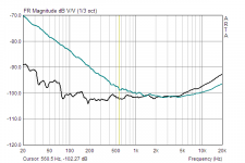
thank you for the report. It is what I wanted that we all see. In attachment I send picture of single channel (black) and dual channel (green) measurements for sound card Focusrite Scaralett 2i2. As you see result in single channel mode is almost excellent. What happens in dual channel mode. There are several possible source of errors:
1) in loopback mode (in unbalanced connection) we have ground loop (that is why I decouple I/O ground with 1k resistor in ARTA measurement box)
2) soundcard input channels have large crosscoupling
3) reference signal has high distortion
4) sometimes bad contacts also make problems
All this cases should be checked.
Further you have noticed some 6dB lower noise floor with SS than with PN. It is normal as PN needs averaging to reach SS dynamics. ARTA generates 9-12dB larger rms value for SS then for PN. Averaging rises S/N proportionally with square root of number of averages.
Ivo
Attachments
Ivo, I'm not clear on how you got that measurement. Just to dispel my confusion, could you detail the test setup and software settings? Thanks.
Where I've seen the Scarlett 2i2 fall down has been high frequency distortion. Good enough for speaker testing, but not so for electronics.
I'm still searching for a USB interface that gives same or better performance than my M-Audio 192 at a less-than-breathtaking price.
Where I've seen the Scarlett 2i2 fall down has been high frequency distortion. Good enough for speaker testing, but not so for electronics.
I'm still searching for a USB interface that gives same or better performance than my M-Audio 192 at a less-than-breathtaking price.
Hi Sy,
This was the test on how much input noise is present in the measured FR. The lower is this level the more dynamic range we have ( in single channel mode case it is the excellent 90 dB). For this measurement input is shorted (or left open) and other input is
- short circuited in single channel measurement (reference excitation channel signal is taken from memory)
- connected to sound card output - in dual channel measurement (reference excitation channel signal is measured o get proper timing information).
Ivo
- connected to sound card output - in dual channel measurement (reference excitation channel signal is measured o get proper timing information).
So basically, what you're doing is the measurement outlined in section 4.2 of the manual?