You might consider using a Lock-In Amplifier to recover the input sinusoid, in the presence of large amounts of noise. Like, a signal-to-noise ratio of 0.1 -- noise magnitude 10X larger than signal magnitude.
Here is Wikipedia's article and
Here is a hobbyist's implementation which measures tiny voltages in order to calculate tiny resistances.
Here is an application note from Cypress Semiconductor showing how they implemented a Lock-In amplifier.
This idea seems broadly similar to my synchronous_detector+low_pass_filter circuit, perhaps some of the subtleties of this idea have escaped me, I will need to reread and try to find some more info on lock in amplifiers.
Thanks again Mark.
Given that there is some debate over the correct method for carrying out the CCS impedance measurements, I am going to repeat a number of the previous current source tests, in order to compare. Perhaps someone with a better head for mathematics, than me, can try to analyze the two methodologies to make some sense of the differences ( there are differences noted already ) I am still gathering together the details and then I will publish them.
From now on the method without the jfet will be called The Low side Method and the method with the jfet will be called The High side Method.
From now on the method without the jfet will be called The Low side Method and the method with the jfet will be called The High side Method.
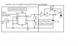
I found this: DIY Lock-in Amplifier
It uses an AD630 as the four quadrant multiplier but I have an MPY634 I think I should be able to use this instead.
It uses an AD630 as the four quadrant multiplier but I have an MPY634 I think I should be able to use this instead.
Last edited:
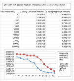
Comparison of the two methods on a j201 CCS, see attached.
Attachments
Last edited:
Quick update.
I have increased amplifier gain to around x10 000 ( 80db ), noise is a bit of a problem, but I'm going to be using an lt1128 in the first stage, which should help, I'm thinking also of adding a 3 pole low pass filter with cutoff of around 50Khz.
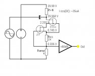
With the present amplifier with 2 x NE5534 and a TLE2141, I was able to measure 330 Megohm with a j201 with 49K9 source resistor and 30vdc across the current source. I would liked to have tried higher voltages but none of the jfets I have can operate above 30 V.
Noise level with zero test signal is around 4mV RMS output from the amplifier, this includes noise generated by the CCS transistor.
Iam deducting the noise part as such:
signal _without_noise = √((V_measured)^2 - (Vnoise)^2)
The measurement was made with the low side method.
I have increased amplifier gain to around x10 000 ( 80db ), noise is a bit of a problem, but I'm going to be using an lt1128 in the first stage, which should help, I'm thinking also of adding a 3 pole low pass filter with cutoff of around 50Khz.
With the present amplifier with 2 x NE5534 and a TLE2141, I was able to measure 330 Megohm with a j201 with 49K9 source resistor and 30vdc across the current source. I would liked to have tried higher voltages but none of the jfets I have can operate above 30 V.
Noise level with zero test signal is around 4mV RMS output from the amplifier, this includes noise generated by the CCS transistor.
Iam deducting the noise part as such:
signal _without_noise = √((V_measured)^2 - (Vnoise)^2)
The measurement was made with the low side method.
I recall a preamp manufacturer claiming they had jfets factory selected for ~2x the nominal V rating of the series - so maybe you can just find a good one
and there are very high V MOSFET - range of Idss from mA on up - but their parasitic C are generally larger
and there are very high V MOSFET - range of Idss from mA on up - but their parasitic C are generally larger
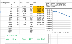
I have managed to break the 1 Gohm barrier today, albeit only at 20 Hz!
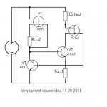
It is a 2 jfet circuit , see attached.
The measured result was 1.74 Gohm at 20 Hz, though it started to roll off almost immediately afterwards.
This measurement was achieved by restricting the bandwidth of the amplifier. The 3db point was at 780 hz approximately, achieved simply by putting a 6.8n capacitor in the feedback network of the third opamp in the amplifier.
More details to follow later
Attachments
The full set of results for the 2 jfet CCS. As you can see the first four results are all over 1 Gohm.
Attachments
Last edited:
If your data is correct it says that Richard Jaeger's current source with bootstrapped JFET cascode, from 41 years ago (post #260) , seems to work rather well today.
By the way he's now a distinguished Emeritus professor at Auburn University in the US: (web page)
By the way he's now a distinguished Emeritus professor at Auburn University in the US: (web page)
Looks like post 353 schematic with shunt feedback leg's pullup changed from 39K to current source.I was thinking about trying out this idea:
Looks like post 353 schematic with shunt feedback leg's pullup changed from 39K to current source.
It is, however I am thinking that the bf244 jfet cascode would serve to increase impedance even further. I do not have the means to simulate at the moment so it's a bit of a guess, bringing together in one circuit a number of ideas that have come to light throughout the thread.
Near the beginning of this thread someone posted a link where a guy called Gary Pimms had made some CCS measurements and claims to have measured over 100 Gohms with a DN2540 based cascode CCS, he does not include a schematic of his CCS' The method he used appears to be very similar to the low side setup that I've been using, he only used a 40db amplifier, though he used a computer to digitize and process his test signals ( probably could clean up a lot of noise and other hash that would be present with such a low level signal.
Gary Pimms CCS measurements
I think that I might try getting in touch with this guy to see if he's willing to share the details of the CCS' that he measured.
Gary Pimms CCS measurements
I think that I might try getting in touch with this guy to see if he's willing to share the details of the CCS' that he measured.
It is, however I am thinking that the bf244 jfet cascode would serve to increase impedance even further. I do not have the means to simulate at the moment so it's a bit of a guess, bringing together in one circuit a number of ideas that have come to light throughout the thread.
I predict that when you do simulate it, you will discover that the helper stage (shunt feedback amplifier Q1) drives a relatively low impedance load at its collector; namely, two base-emitter junctions in series. I predict you will discover this impedance is somewhere in the neighborhood of 55-60 ohms at the bias point you have chosen. I predict that you will discover that circuit performance hits an asymptote, and stops getting better, when the incremental resistance "rload" of Q1's pullup circuit becomes negligible compared to 60 ohms. Namely, when rload > 6K ohms. I predict you will discover that performance is the same whether rload is 10K ohms, 39K ohms, 400K ohms, or 40 Megohms. Because rload is in parallel with 60 ohms.
Attachments
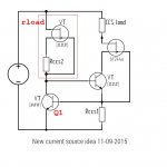
I predict that when you do simulate it, you will discover that the helper stage (shunt feedback amplifier Q1) drives a relatively low impedance load at its collector; namely, two base-emitter junctions in series. I predict you will discover this impedance is somewhere in the neighborhood of 55-60 ohms at the bias point you have chosen. I predict that you will discover that circuit performance hits an asymptote, and stops getting better, when the incremental resistance "rload" of Q1's pullup circuit becomes negligible compared to 60 ohms. Namely, when rload > 6K ohms. I predict you will discover that performance is the same whether rload is 10K ohms, 39K ohms, 400K ohms, or 40 Megohms. Because rload is in parallel with 60 ohms.
I think you are probably right, in that the top left jfet would not yield any significant increase in impedance, though it would probably help with power supply noise/ripple rejection.
My principle interest was in using the top right jfet to improve the performance of the ring of two bipolar transistor CCS.
Using a j201 in the cascode position, see attached schematic, i have made preliminary tests suggesting around 40 Gohm at 20Hz. With the gate connected to the top end of the CCS transistor, the DC voltage across the ring of two was too low for it to work properly, so I split the 39k bias resistor into two 18K with a 100u capacitor to clean up the bias supply. The capacitor made a considerable difference to the ring of two even in the absence of the jfet.
Noise is a problem at this level so improvements to the amplifier are becoming mandatory.
For one it needs to be better constructed. I have an LT1128 opamp to use in the first stage of the amplifier. I may opt for a differential input stage as 50Hz interference is still an issue, if it remains a problem after that another option is battery powering the amplifier, Gary Pimms done that in his setup.
Attachments
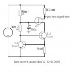
You changed them to 18K! Why?Split the 39K Rbias into two series resistors, 20K each, and connect a 330uF bypass capacitor between the middle node of the 20K resistors, and ground
You changed them to 18K! Why?
They were handy and not significantly different to 39K.
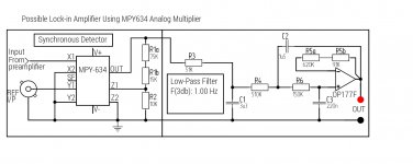
After quite a bit of reading on lock in amplifiers, I (think) have optimized the low pass filter using the components I had available, yes I actually had an OP177F, lying around!
Resistor values in the filter are high by virtue of the fact that non electrolytic capacitors had to be used because of the very low DC voltages involved, which ruled out the other bipolar opamps I had available. Of the jfet input opamps, none had the sort of precision necessary for a delicate measurement like this. The op177f has 200Gohm input resistance in the common mode, almost as high as a jfet input device.
See attached. I have still to assemble this section to see if it works as expected.
Attachments
- Status
- Not open for further replies.
- Home
- Amplifiers
- Solid State
- How do you calculate impedance of a current source?