just a statement of LM4562 linearity vs THAT chip designed decade earlier, undoubtedly on an a open fab process from that eraI would’ve used the Whitlock’s input chips and implemented the capacitive bootstrap technique as well, except that the distortion performance is not good enough in my view.
the bootstrapping shouldn't have any additional distortion consequence - in fact should reduce most of the cap's nonlinearity and DA effects for the common mode leaving even less to diff out
Last edited:
I did not see any limits on maximum gain, nor on maximum attenuation, achievable with the active gain block. Have I missed that?
Are there some limiting resistors built into the PCB?
Are there some limiting resistors built into the PCB?
I did not see any limits on maximum gain, nor on maximum attenuation, achievable with the active gain block. Have I missed that?
Are there some limiting resistors built into the PCB?
Jan had pointed out that in fact there aren't any in the design, probably in order to not mess up the perfect tracking only dependent on rotation angle of the pot with both channels on the same spindle. There was an alternative approach which Jan had offered to share shortly.
just a statement of LM4562 linearity vs THAT chip designed decade earlier, undoubtedly on an a open fab process from that era
the bootstrapping shouldn't have any additional distortion consequence - in fact should reduce most of the cap's nonlinearity and DA effects for the common mode leaving even less to diff out
I see - that's indeed very interesting!
I suggest we keep track of potential design enhancements or variations for kind of a "version 2.0". Currently we have two already - Whitlock's diff amp input common mode bootstrapping, and alternatives to pot / limiting resistors
Last edited:
Alright, I have set up an Excel Online sheet to collect current interest.
Please go to http://1drv.ms/1JPOfR6 , enter your username and the amount of 'bare' PCBs and/or fully built modules you are interested in. No obligation for now, just to collect an estimate on cost and volumes.
Thank you,
Robert
Please go to http://1drv.ms/1JPOfR6 , enter your username and the amount of 'bare' PCBs and/or fully built modules you are interested in. No obligation for now, just to collect an estimate on cost and volumes.
Thank you,
Robert
How many modules are needed for stereo?
The modules are stereo, so one.
I am building a P - P with some small changes.
It should play tomorrow.
Lonesome but faster ....
It should play tomorrow.
Lonesome but faster ....
BTW I had 1000 free boards which are all given out
Jan
Would be interesting (and probably impossible) to find out how many were build from that 1000 and how many are lingering in drawers.
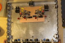
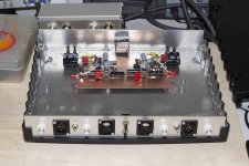
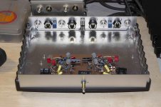
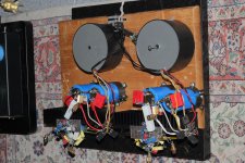
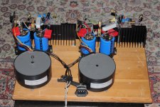
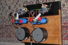
Here is how it looks.
I took NE5532. i have a lot of them because i wanted to build Selfs Grid Amp but i never did.
Inverted they are realy good because they have excellent transfer linearity ( Groner ).
I also may try biasing into Class A from the positive side ( Self in his book about electronic crossovers ).
The red jumpers are obsolete. i added them because i di not understand why they are in the schematic.
Yes Jan, i should read more careful but i do not read only this but a lot more.
Actually i read all the time, even on the to.....
I have bal and unbal in and out and also an input switch for 1 bal source and one unbal source.
That is good in my system. My CD player is unbal and my phono bal.
I mostly use a tube poweramp that has unbal input.
Attachments
This may interest Jan :
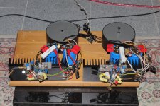
I build the Vanderkoy amp from Linear Audio in higgledy-piggledy style.
Trusting my soldering it was put in the system without testing and that resulted in big trouble.
I know this was risky but organisation is the last resort of the troubled mind.
One thing was that it was humming like cazy.
I destroyed two very expensive wideband drivers with ALNICO magnets and a rare tweeter in a replacement box.
OK; pause.
Several days later i went back to read the article one more time ( rtfm, yes Jan ).
I build the balanced version and the schematic had an error.
I than rebuild the amp with the corrected placement of the input components.
That made the problem a bit less problematic but the humm was still too high for enjoyment.
Again back to the text and then i found the solution.
The source resistor is a combination of the output impedance of the preamp plus the input resistor, in this case 1kOhm.
I put a trimmer of 50kOhm parallel to the 1kOhm. This way i can adjust for lowest amount of hum, compensating the output resistance of the preamp.
Another problem is the rather high DC offset, around 50mV in both channels in my build.
I found a solution for this too without resorting to a servo.
And then the diodes in the PSU ...
Maybe more on ETF.
Attachments
Last edited:
Might I suggest obtaining a pair of crappy "full-range" drivers with wires pre-attached for easy and fast initial testing. They can be part of the clutter... get three so you can fry one and still be in business... Sad to fry rare stuff...
Yes, since then i do exactly this.
Anyway, i am disappointed that i did not get it right, right away.
I am a bit naive.
Creativity and naivity are brothers.
Anyway, i am disappointed that i did not get it right, right away.
I am a bit naive.
Creativity and naivity are brothers.
They have a lot of stuff here :
HiFi/Car-HiFi/Video/TV - Lautsprecher - Lautsprecher-Chassis - Pollin Electronic
HiFi/Car-HiFi/Video/TV - Lautsprecher - Lautsprecher-Chassis - Pollin Electronic
Jan had pointed out that in fact there aren't any in the design, probably in order to not mess up the perfect tracking only dependent on rotation angle of the pot with both channels on the same spindle. There was an alternative approach which Jan had offered to share shortly.
Yes, you are quite right with the reason NOT to use series Rs. Hans Polak has designed a small add-on PCB with a quad of reeds to get around it. He has kindly agreed to share it and I just posted it here: Downloads | Linear Audio
I believe he still has a a few PCBs left...
Jan
This may interest Jan :
I build the Vanderkoy amp from Linear Audio in higgledy-piggledy style.
Trusting my soldering it was put in the system without testing and that resulted in big trouble.
I know this was risky but organisation is the last resort of the troubled mind.
One thing was that it was humming like cazy.
I destroyed two very expensive wideband drivers with ALNICO magnets and a rare tweeter in a replacement box.
OK; pause.
Several days later i went back to read the article one more time ( rtfm, yes Jan ).
I build the balanced version and the schematic had an error.
I than rebuild the amp with the corrected placement of the input components.
That made the problem a bit less problematic but the humm was still too high for enjoyment.
Again back to the text and then i found the solution.
The source resistor is a combination of the output impedance of the preamp plus the input resistor, in this case 1kOhm.
I put a trimmer of 50kOhm parallel to the 1kOhm. This way i can adjust for lowest amount of hum, compensating the output resistance of the preamp.
Another problem is the rather high DC offset, around 50mV in both channels in my build.
I found a solution for this too without resorting to a servo.
And then the diodes in the PSU ...
Maybe more on ETF.
Joachim, sorry to hear that! Do you mind if I forward this to Vanderkooy et al? BTW there was a correction to the article here: Oops | Linear Audio (3rd or 4th article down).
And yes we can discuss it again at ETF.
Jan
Yes, you are quite right with the reason NOT to use series Rs. Hans Polak has designed a small add-on PCB with a quad of reeds to get around it. He has kindly agreed to share it and I just posted it here: Downloads | Linear Audio
Many thanks Jan for sharing Hans' concept and for making his document available, much appreciated! Indeed a very worthwhile addition.
Robert
Yes, Jan, you can forward this to Vanderkooy.
It is a good sounding and simple amp.
By the way i set the idle to 200mA.
I thought that this sounds a bit more full bodied then 100mA, anyway.....
It is a good sounding and simple amp.
By the way i set the idle to 200mA.
I thought that this sounds a bit more full bodied then 100mA, anyway.....
Hans Polak has designed a small add-on PCB with a quad of reeds to get around it. He has kindly agreed to share it and I just posted it here: Downloads | Linear Audio
Gents, just for my understanding (and paranoia) please: From looking at the schematic in Hans' document, there are quite a few more components and more real estate in the signal path with his PCB, compared to the R5 pot in Bruno's original design. Can we be sure that there is no detrimental effect or compromise by this (inductance? loops?) on the excellent layout and measurements of Bruno's design? How can that be achieved?
Last edited:
- Home
- Source & Line
- Analog Line Level
- BPPBP - Bruno Putzey's Purist Balanced Preamp (well a balanced volume control really)