Impossible.Is it possible that the reservoir cap is much smaller than 450uF or disconnected?
If there were some ripple left over the DVM would read them as AC voltage on the cap, which it does not (0mVAC).
What do you mean too large?450uF would be far too much for a 5Z4 to feed, and quite large for even a silicon rectifier.
In Single-Ended the max current is at idle, which should result in maximum ripple.
Also, the larger the caps the less ripple there is at large current draws, especially with a choke and another cap.
At the second cap there is 0mVAC according to my DVM.
So where are the missing 50V? Mystery...
Impossible.
If there were some ripple left over the DVM would read them as AC voltage on the cap, which it does not (0mVAC).
What do you mean too large?
In Single-Ended the max current is at idle, which should result in maximum ripple.
Also, the larger the caps the less ripple there is at large current draws, especially with a choke and another cap.
At the second cap there is 0mVAC according to my DVM.
So where are the missing 50V? Mystery...
A little thing called, Inrush Current....
Valve rec's datasheet seldom quote first-cap larger than 50uF....
Check the value of your own rec in its data-sheet, it WILL NOT be 470uF thats for sure....
Its a typical Chinese thing to use a way too big 1st cap in their amps-- basically because they are solid-state designers meddling with valves....
My very similar chinese kit amp has a 47uf capacitor there after the 5Z3P rectifier and before the choke.
Is it a mistake in the schematic?
You have plugged in a solid state rectifier rather than putting in diodes yourself? does it have built in resistance to simulate the voltage drop of a valve rectifier rather than overwhelming the existing circuit with greatly increased voltage?
Is it a mistake in the schematic?
You have plugged in a solid state rectifier rather than putting in diodes yourself? does it have built in resistance to simulate the voltage drop of a valve rectifier rather than overwhelming the existing circuit with greatly increased voltage?
I do not use tube rectifier, I use SSR which I built from two 1N5408 diodes.
The SSR is built according to this: SSR
The caps rated 450V and a I don't see the capacitance value anywhere, but I see the code.
According to the code I found the datasheet, according to size (25x35) I found the capacitance value.
Its caps are 450V, 150uF.
Datasheet: PDF
The SSR is built according to this: SSR
The caps rated 450V and a I don't see the capacitance value anywhere, but I see the code.
According to the code I found the datasheet, according to size (25x35) I found the capacitance value.
Its caps are 450V, 150uF.
Datasheet: PDF
Last edited:
No Need to be rude
You said you installed a SSR, you did not say you built it or what you used.
You said you installed a SSR, you did not say you built it or what you used.
At this stage, the amp as delivered was different to the schematic you were given, and you have made quite a number of modifications, it is probably time to redraw it as constructed
I question the original schematic's accuracy, did they really use 150uF as the first capacitor for the 5Z4P?
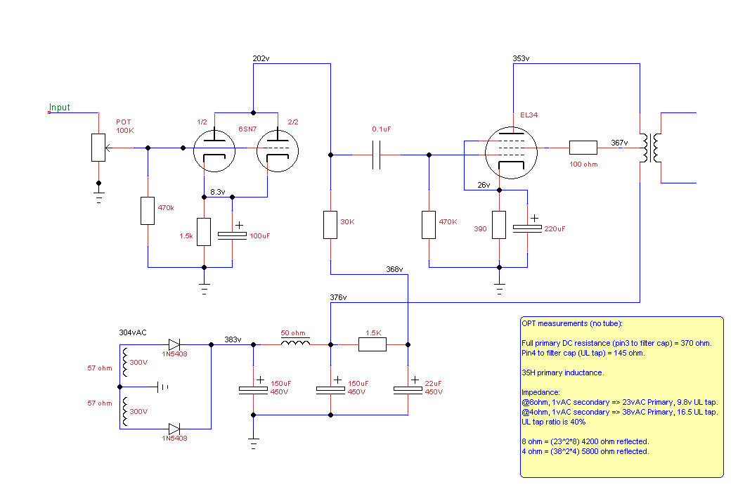
This is the real values and voltage measurements of my amp.
Note that from after the Choke (376v point) the amp is doubled, hence the current through the Choke is from both sides.
Drawn with TinyCAD.
Last edited:
That looks nice, so the questions is on the power supply voltage, correct?
Thanks.
Yes, why does the DC measurement does not retain the 1.414 ratio from AC measurement.
304*1.414 = 430vDC
But I only read 383vDC, 50v are missing.
Holy smokes! Thanks for that!The 1.414 multiplier is for un-loaded voltage only, what you have is actually something like this.
Very useful.
I guess everything is perfectly fine and no longer a mystery. 😀
Yeah 1.3 is more realistic for a HV supply.
You might approach the 1.4 for a supply such as a bias supply where you are just supplying a voltage source with negligible current flow
You might approach the 1.4 for a supply such as a bias supply where you are just supplying a voltage source with negligible current flow
It concludes that in practice it's impossible to guess the AC to Filtered DC ratio (assumed to be 1.414) in a real amp without knowing the current draw and resistance of secondary winding.
In the simulation,
The 2.7k resistor dictates the current of 140mA that my amp actually draws over the Choke.
The interesting thing is that the power transformer resistance (57 ohm) distorts the waveform resulting in a wrong RMS reading of 300vAC with my DVM.
No voltage is mysteriously vanished, it's just wrong assumptions and using cheap DVM instead of a scope.
Thanks
Last edited:
I want to run the amp with only one channel.
How dangerous is it for the single ended OPT when turning on without a power tube and without a load (infinite resistance at secondary)?
There will be no current through the primary of the OPT but there will be a sudden B+ voltage swing at turn on. Any danger?
How dangerous is it for the single ended OPT when turning on without a power tube and without a load (infinite resistance at secondary)?
There will be no current through the primary of the OPT but there will be a sudden B+ voltage swing at turn on. Any danger?
Last edited:
Side by Side A/B, SS vs Tube Comparison:
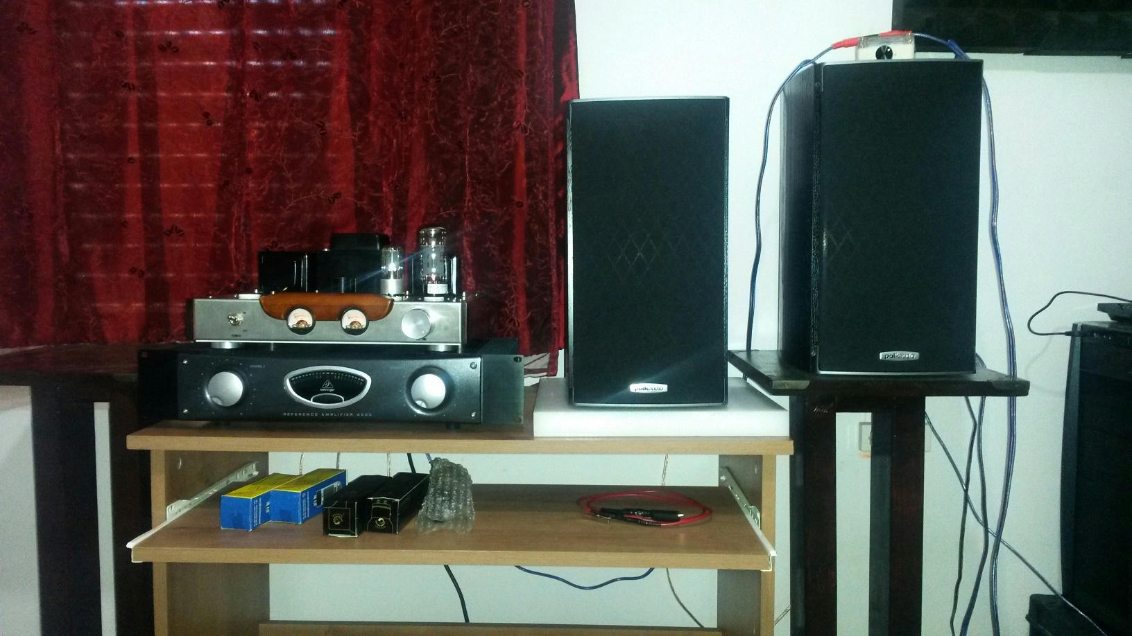
One channel of each amps was connected, SS Left, Tube Right.
Using my DAW I played a song (mono down-mix) or pink noise to either left or right channel.
On top of the right speaker is my Stepped Attenuator for the SS amp because it's a lot louder.
Speakers are close together to entertain same room modes from my listening position.
After balancing the volume I immediately noticed that the tube amp has more Balls and more "In Your Face" type of sound which I quite like.
I placed an EQ in the SS track any tried to match the SS to the Tube sound.
After a short while I managed to make the SS sound almost the same as the Tube.
Not to my surprise, the boosted frequencies of the EQ looked like the Impedance of the speaker which tube amps like to follow.
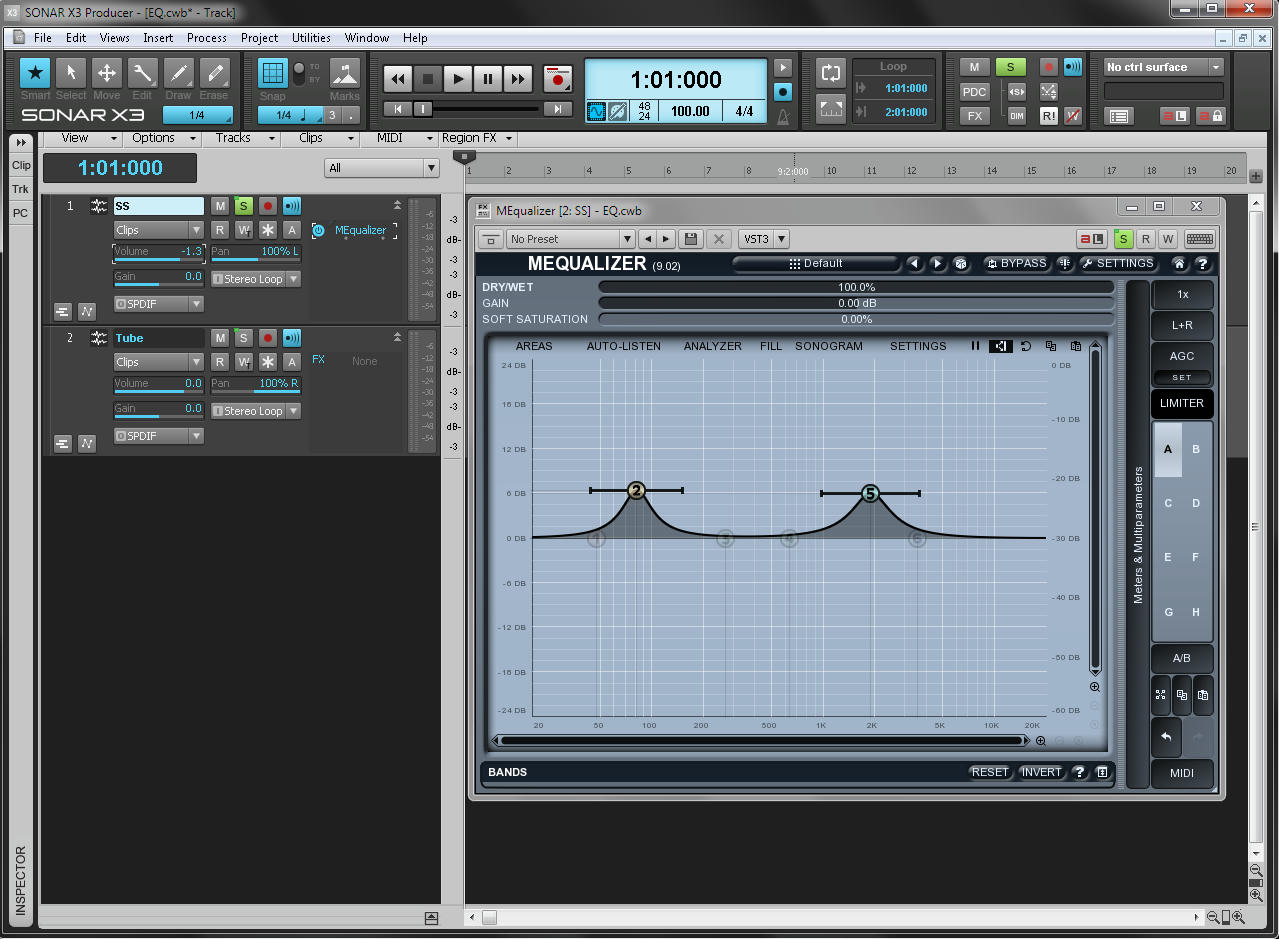
The boost is around 6db to 8db in 2k and 80Hz to my ears, that produces the fuller more round and ballsy sound.
So in my opinion the Polk RTi A3 speakers sound nice and Raw with tube amps especially for Rock and Metal music.
I could make the Tube amp sound exactly like the SS with more NFB but that would just destroy its uniqueness and the reason to have a tube amp.
My amp is wired as Ultra-Linear without NFB and in my opinion a tad less NFB is a good thing because it creates the magic of matching a good sounding speaker
(impedance) in which these frequencies will be boosted and will create the unique sound of that setup.
On the other hand, I can make a SS amp sound like a Tube amp with slight EQ and some tube clipping plugin, but where's the fun, danger and shiny lights in that? 😀
One channel of each amps was connected, SS Left, Tube Right.
Using my DAW I played a song (mono down-mix) or pink noise to either left or right channel.
On top of the right speaker is my Stepped Attenuator for the SS amp because it's a lot louder.
Speakers are close together to entertain same room modes from my listening position.
After balancing the volume I immediately noticed that the tube amp has more Balls and more "In Your Face" type of sound which I quite like.
I placed an EQ in the SS track any tried to match the SS to the Tube sound.
After a short while I managed to make the SS sound almost the same as the Tube.
Not to my surprise, the boosted frequencies of the EQ looked like the Impedance of the speaker which tube amps like to follow.
An externally hosted image should be here but it was not working when we last tested it.
The boost is around 6db to 8db in 2k and 80Hz to my ears, that produces the fuller more round and ballsy sound.
So in my opinion the Polk RTi A3 speakers sound nice and Raw with tube amps especially for Rock and Metal music.
I could make the Tube amp sound exactly like the SS with more NFB but that would just destroy its uniqueness and the reason to have a tube amp.
My amp is wired as Ultra-Linear without NFB and in my opinion a tad less NFB is a good thing because it creates the magic of matching a good sounding speaker
(impedance) in which these frequencies will be boosted and will create the unique sound of that setup.
On the other hand, I can make a SS amp sound like a Tube amp with slight EQ and some tube clipping plugin, but where's the fun, danger and shiny lights in that? 😀
Last edited:
Frequency Response and Distortion measurements:
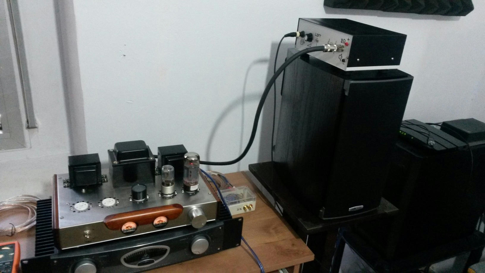
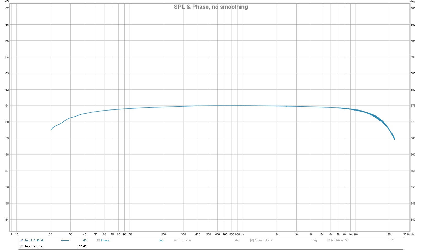
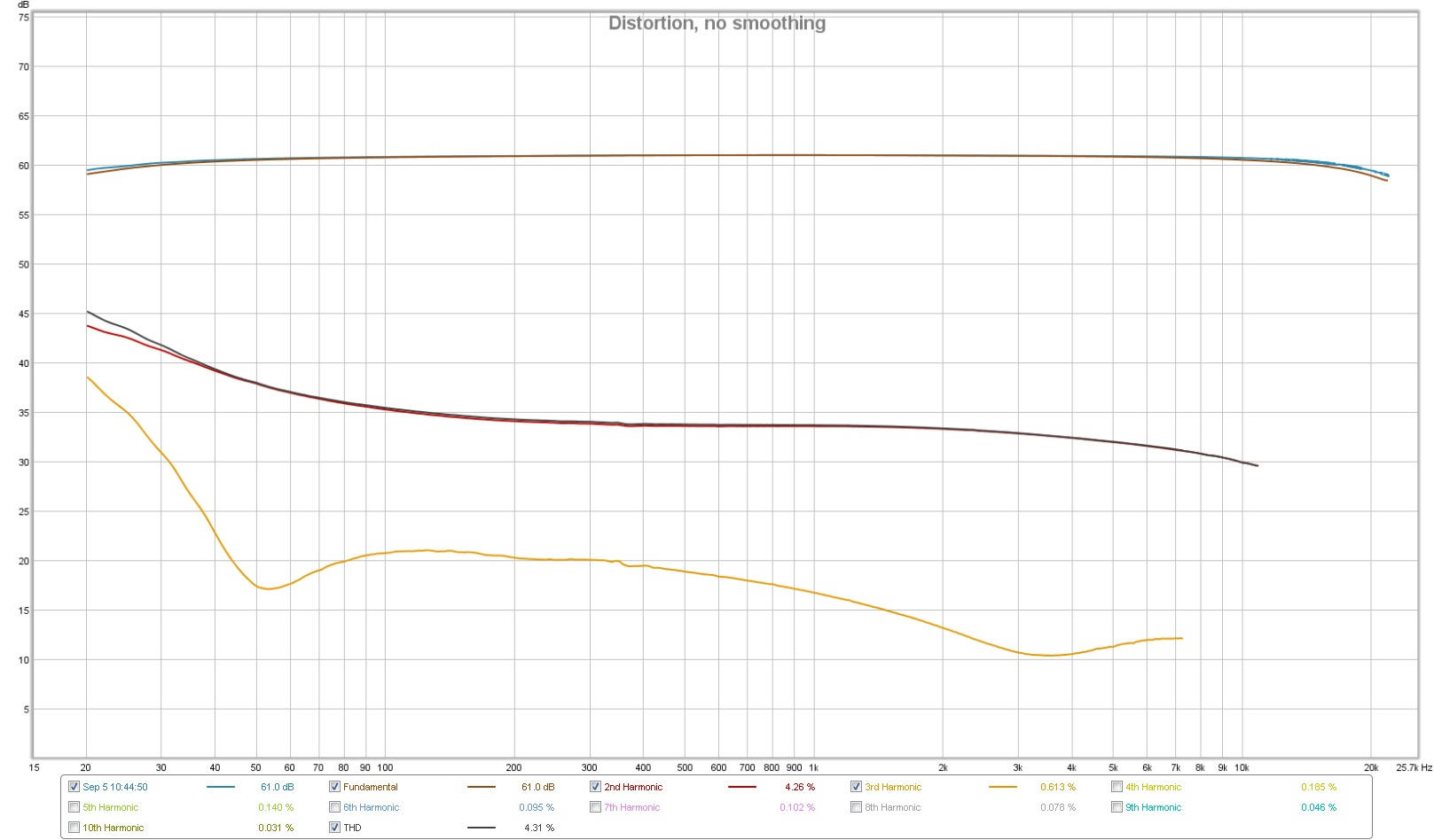
The tube amp speaker output goes into an 8ohm 200W dummy load, from there (in parallel) through a 10k and 1k pot (voltage divider) into the input of my audio card.
Measurements with 1kHz 0.78vAC RMS at amp input (1.1vAC Peak), which my mini DAC outputs.
The output transformer sings, as expected.
The frequency response is not bad for such tiny transformers.
-0.5db at 40Hz and 13kHz, -1db at 26Hz and 17 kHz, -1.5db at 20Hz and 20kHz.
Distortion level is 4.3% (-27db) 2nd harmonic, and 0.6% (-44db) 3rd, at mentioned input.
Below 50Hz distortion levels of 3rd harmonic sharply rises to a combined 12% THD at 30Hz, 20% at 20Hz.
Not bad for pleasant music reproduction, but nowhere near the performance of a SS amp.
In my DAW I created two tracks, one with the original (mono) track (or signal generator), the other with the input from the dummy loaded tube amp.
This gave me the option to compare the direct signal vs the signal processed by the tube amp, and also see the tube amp FFT (spectrum analyzer) with a plugin.
Listening through my studio monitors (near by) or my studio headphones.
To tell you the truth, I can't hear the difference with music between direct and after tube amp, when driving the tube amp full tilt.
The peaks distort 4.4% mainly with 2nd harmonic and music does not reach the peaks constantly as a sinewave would.
-1.5db at 20Hz 20kHz is not something I would fuss about, and at 40Hz (9% 2nd, 1% 3rd) is inaudible with music.
It's a tube amp, not pristine by today's standard but hey, it's a piece of history... and it's shiny. 🙂
This thread looks abandoned, but I recently got that amp as well and basically did the same modifications. Also installed the grid stopper for the 6SN7 tubes (3.6kohm). The only thing that I noticed is that secondaries on OPTs are not grounded at all. Moreover, there are those VU meters across secondaries (0 and 8ohm outputs). The VU meters work as they should, even though they are not super sensitive, but when I try to ground all "0" Ohms on secondaries, the arrow on one of the VU meter stays in the middle all the time. Also when I do simultaneous measurements on two secondaries with my oscilloscope it creates lots of weird oscillations (not related to the input signal). I read that it can happen (measurements on non-grounded secondaries). So, I would like to ground my secondaries for safety reasons but I would like to keep my VU meters working as well. So far it does not work (I think the internal resistance, and diode rectification in VU meters might create problems).
- Status
- Not open for further replies.
- Home
- Amplifiers
- Tubes / Valves
- Chinese, Single-Ended, Class A, Questions.