I don't understand your question. How does DC stability come into it? The 'remaining' 30V is across the valve, as I said. To reduce this a little you need a bigger valve; to reduce it a lot you need to use transistors instead.James Freeman said:What do you think will improve the DC stability and provide more current when needed? Where to remaining 30V go?
The Tube rectifier definitely has no place in a hi-fi amplifier.
Tube rectifiers are fine for hi-fi, although not necessary. You won't get much sag as the DC current drawn by a Class A SE amp does not vary by much - maybe increasing by 10% on maximum signal.
No need for sequencing in low power amps - it can do more harm than good. Guitar amps have a 'standby' switch because guitarists expect to see it, not because it does anything useful. The current is max at max signal, but it doesn't vary by much anyway.Fellows, any procedure of warming up the tubes?
Should I wait a few seconds while the filaments heat up?
Although it should not matter because in SE amp the current through the tube is max at idle, and the HT and filaments turn on together.
The 30V across the valve is the lowest voltage it can achieve at that current in that circuit at the B+ the stage is running at--Its Saturated.
--Quite normal.
Valve rectifiers certainly have their place in Hi-Fi amps,--Otherwise original NOS 5U4G for instance wouldn't sell for a £100+ a pop. Original GZ34 NOS (Sure you know THAT type) can go for daft money too!
--Quite normal.
Valve rectifiers certainly have their place in Hi-Fi amps,--Otherwise original NOS 5U4G for instance wouldn't sell for a £100+ a pop. Original GZ34 NOS (Sure you know THAT type) can go for daft money too!
Fellows, please suggest a Pot value for the NFB, the original resistor is 10K.
If anyone familiar with these amps and can suggest a pot the will cover a wide range of NFB.
This will be wired in series with a switch to disconnect the NFB altogether, and maybe a series resistor to prevent oscillation at minimal settings.
bwaslo?
If anyone familiar with these amps and can suggest a pot the will cover a wide range of NFB.
This will be wired in series with a switch to disconnect the NFB altogether, and maybe a series resistor to prevent oscillation at minimal settings.
bwaslo?
Last edited:
Stupid 30 min edit disability... 
Its already wired in Ultra-linear with a 10K negative feedback resistor.
I know Triode needs almost no NFB, UL a little more, and Pentode a lot.
Maybe for Triode a 20K will do, or completely off.
So will a 20K (linear) be high enough for minimal feedback in Triode mode?
Its already wired in Ultra-linear with a 10K negative feedback resistor.
I know Triode needs almost no NFB, UL a little more, and Pentode a lot.
Maybe for Triode a 20K will do, or completely off.
So will a 20K (linear) be high enough for minimal feedback in Triode mode?
Last edited:
Then I'd keep the 10k in there and put about 100k variable in series with it for a fb adjust. That'll give about 15dB range (probably) till Fb is effectivey gone at max R. You'll probably end up using at one extreme or the other.
I would recommend the O/P read through this--
http://www.tubebooks.org/Books/Atwood/Langham 1950 High-Fidelity Techniques.pdf
Great. Cheers for that.
😎
Then I'd keep the 10k in there and put about 100k variable in series with it for a fb adjust. That'll give about 15dB range (probably) till Fb is effectivey gone at max R. You'll probably end up using at one extreme or the other.
For MORE feedback (in Pentode mode) the resistance should be smaller... so isn't the series 10k should be smaller if used with a pot?
Agree, an excellent read.Great. Cheers for that.
😎
Especially the part where he explains how the plate and OPT primary resistance difference effect the damping factor and interact with the speaker impedance.
Maximum power transfer when plate resistance = OPT primary.
Triode plate resistance = 800 ohm.
Pentode plate resistance = 25,000 ohm.
That is why a Triode needs less NFB compared to a Pentode to sound "flatter".
A Pentode is extremely sensitive to speaker impedance and needs a lot of NFB to "fix" the impedance mismatch between plate and OPT primaries.
Last edited:
True, but almost completely irrelevant. We are not aiming for maximum power transfer, but sufficient power transfer at sufficiently low distortion and sufficiently high efficiency.Maximum power transfer when plate resistance = OPT primary.
The 'maximum power transfer' theorem is taught to all first-year EEs, but is almost never used in real life audio electronics. It has some use in RF.
Bear in mind that adjusting NFB changes gain, frequency response, distortion and output impedance.
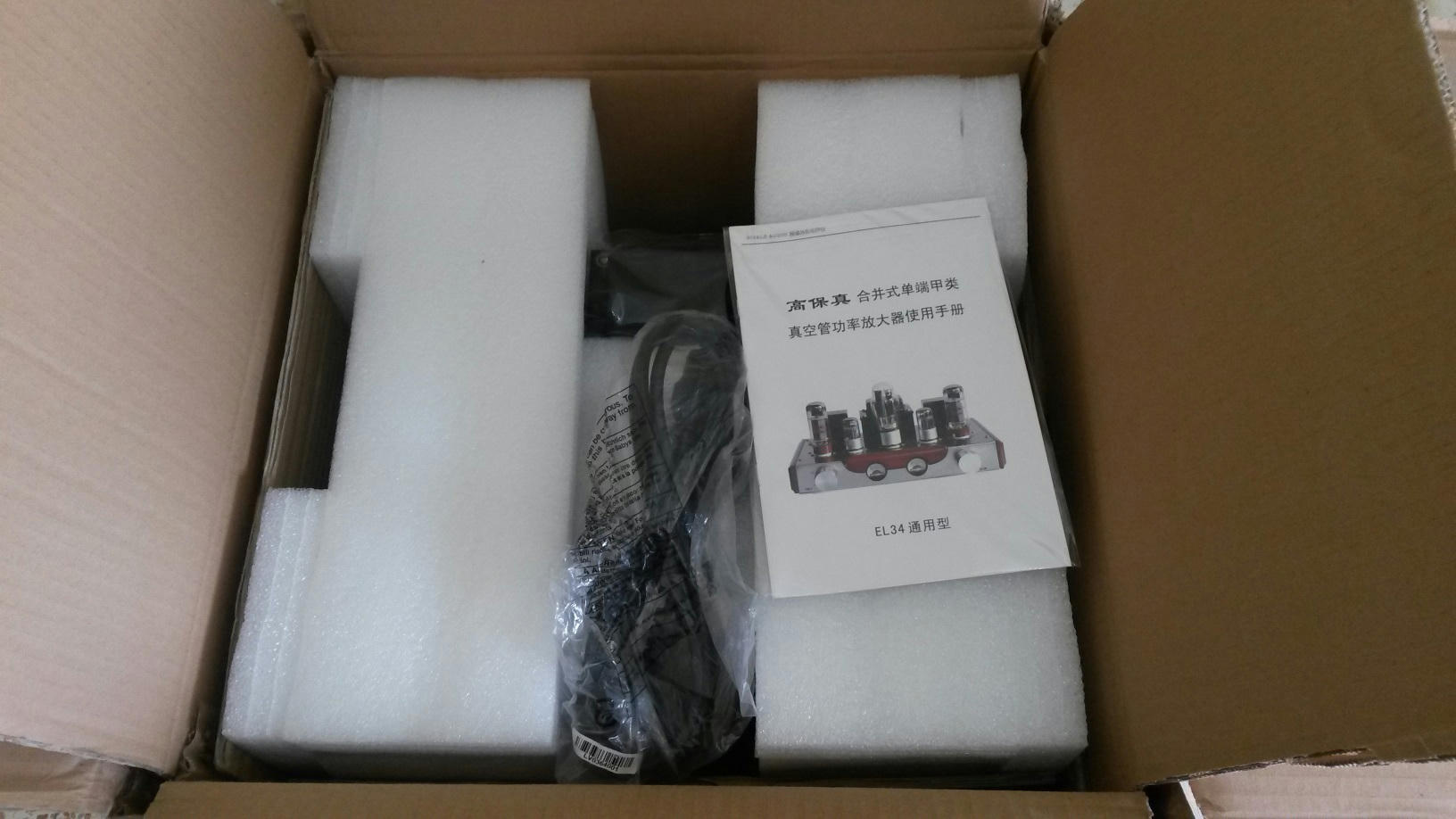
It has arrived!
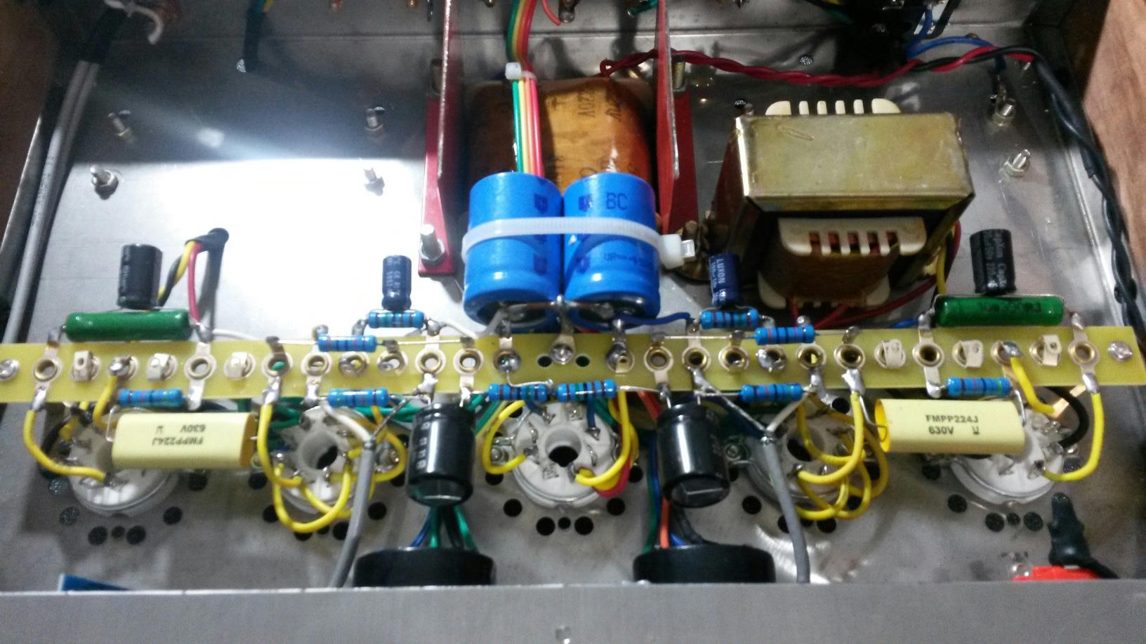
Photos first talk later:
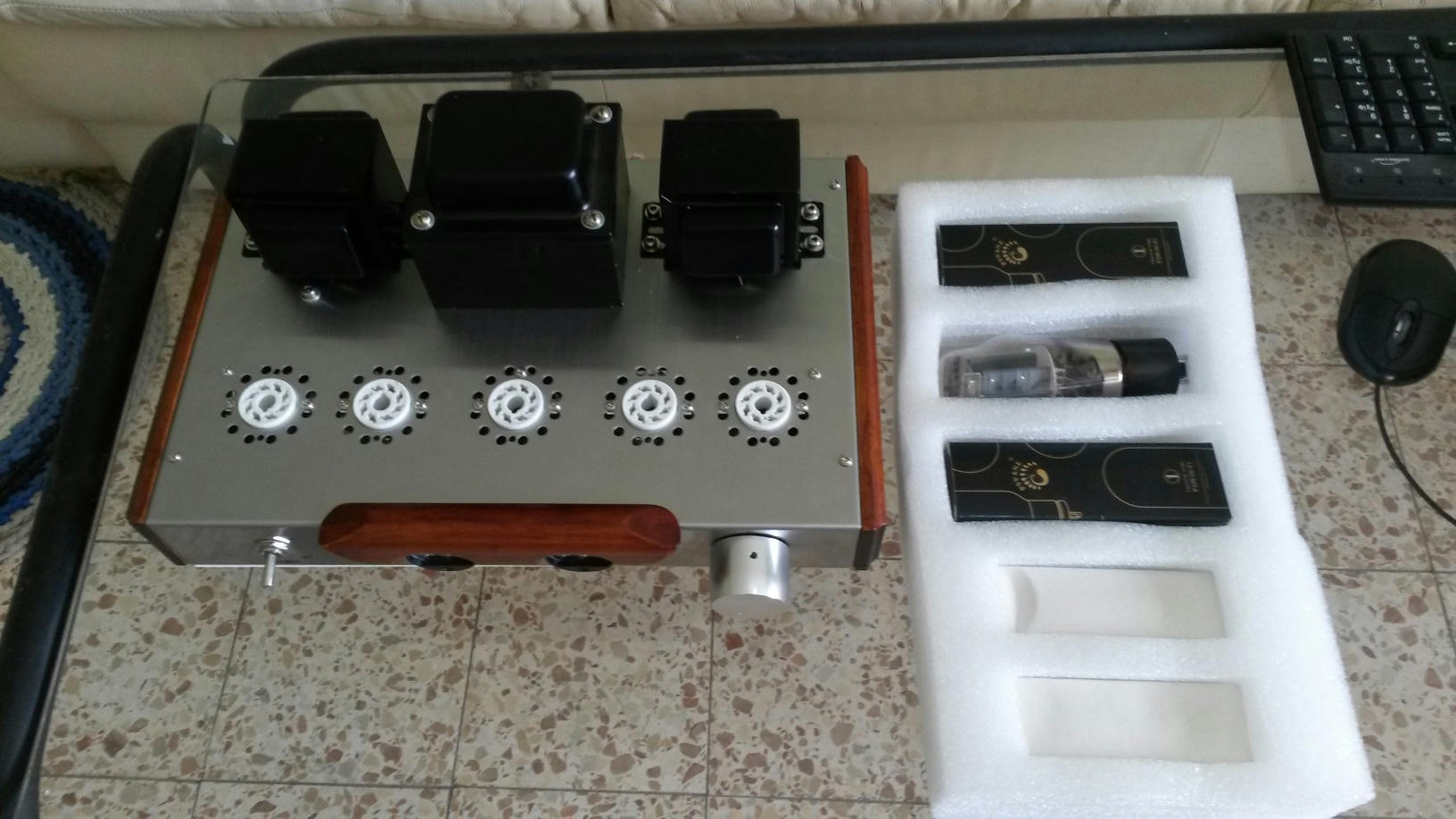
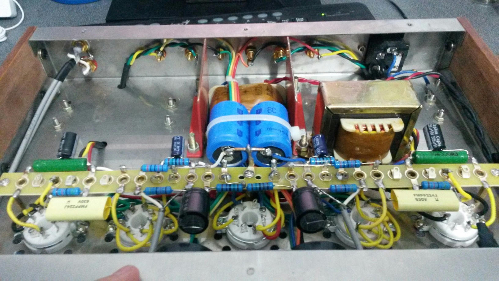
Okay, this sounds and looks Amazing!
Now for the important part;
The build quality and soldering job is OUTSTANDING, I am truly amazed! 😱
All the screws and jacks are tight, pot is smooth and balanced, no hum or hiss, properly twisted filament wiring, properly shielded signal leads, hot glue on RCA jacks to prevent twisting, heat shrink, cable ties, proper grounding, transformer weight standoffs.
Man, I don't believe this is actually a Chinese product...😕
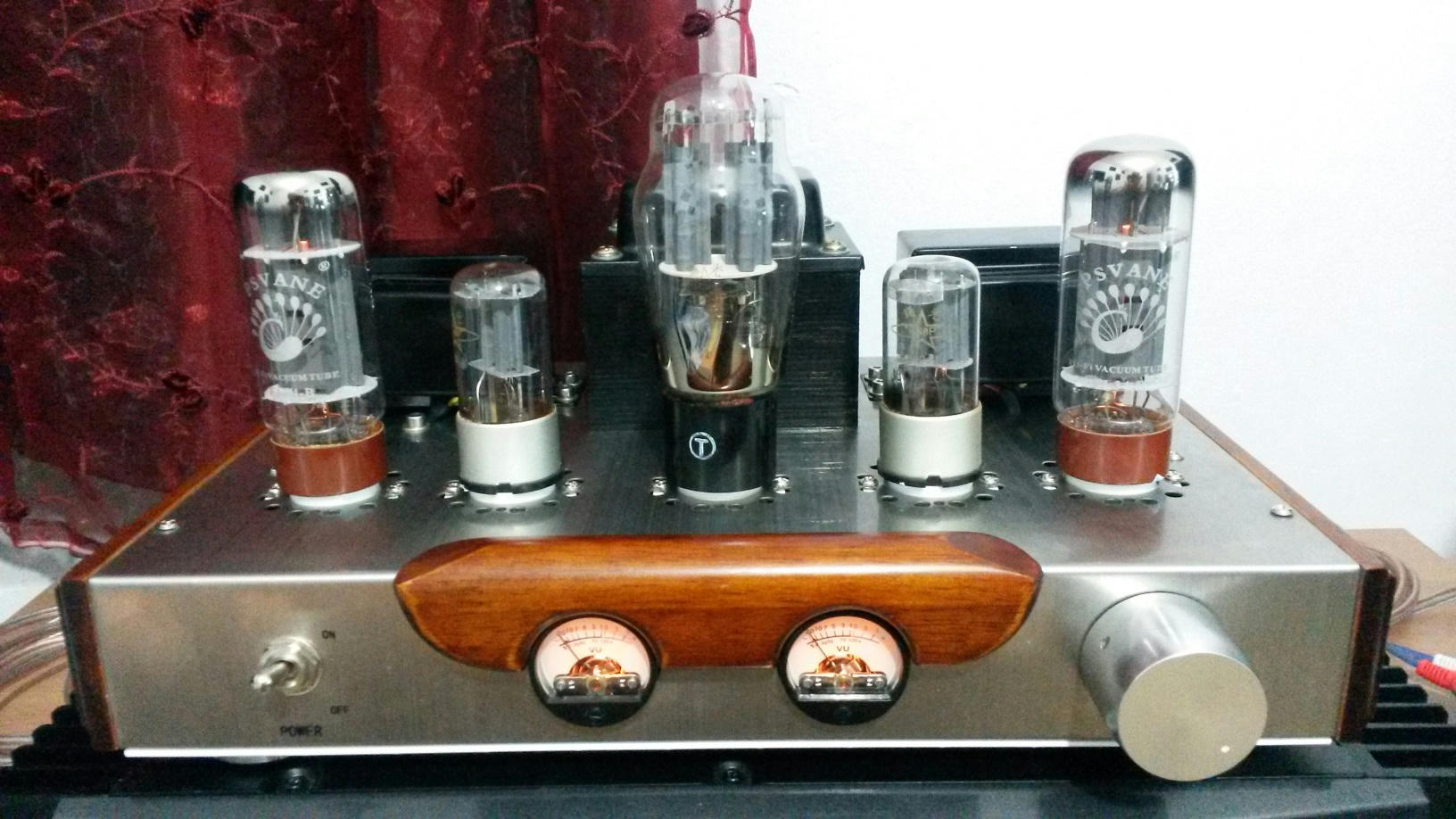
Wired as Ultra Linear without negative feedback, no screen resistor either.
Played a sinewave with max volume (quite painful), can't hear a trace of distortion, no buzzing (third) or octave (second), just pure ear piercing sinewave.
I can clearly hear a 0.03% distortion (-70db second & third) simulated in a DAW with a clipped sinewave, but not with this amp.
This means that the THD of this little amp is low enough for my needs.
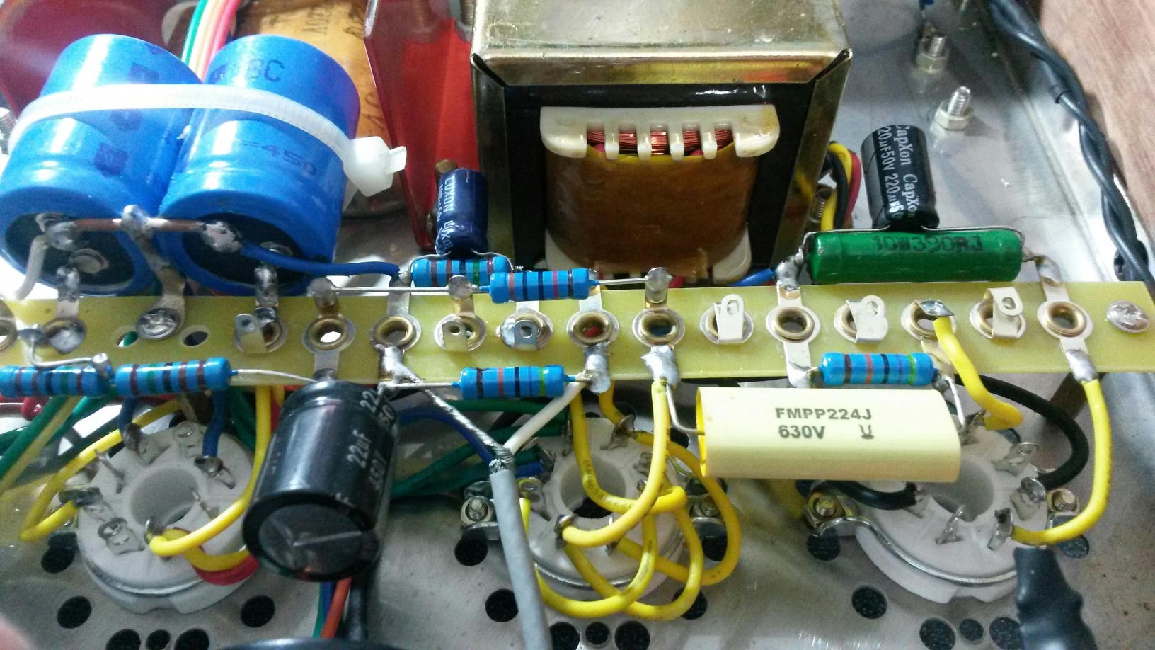
Written on the power Trfx:
Separate 5VAC for rectifier, TWO 3.15 pairs (wired one for each channel), 300VAC.
Measurements to come...
Photos first talk later:
Okay, this sounds and looks Amazing!
Now for the important part;
The build quality and soldering job is OUTSTANDING, I am truly amazed! 😱
All the screws and jacks are tight, pot is smooth and balanced, no hum or hiss, properly twisted filament wiring, properly shielded signal leads, hot glue on RCA jacks to prevent twisting, heat shrink, cable ties, proper grounding, transformer weight standoffs.
Man, I don't believe this is actually a Chinese product...😕
Wired as Ultra Linear without negative feedback, no screen resistor either.
Played a sinewave with max volume (quite painful), can't hear a trace of distortion, no buzzing (third) or octave (second), just pure ear piercing sinewave.
I can clearly hear a 0.03% distortion (-70db second & third) simulated in a DAW with a clipped sinewave, but not with this amp.
This means that the THD of this little amp is low enough for my needs.
Written on the power Trfx:
Separate 5VAC for rectifier, TWO 3.15 pairs (wired one for each channel), 300VAC.
Measurements to come...
Last edited:
The screen resistor is primarily a stopper, so best to include it. The bias source is not particularly relevant, uness you go to higher values (1k and up) when the screen resistor starts to affect (and perhaps stabilise) the bias as well as acting as a stopper.
Measurements and Questions:
300vAC before rectifier tube.
320vDC after rectifier tube on cap.
300*1.414 = 420vDC -> The rectifier drops 100V ???
EL34:
Pin3 (plate) - 290vDC
Pin4 (screen) - 300vDC (higher? *wired as UL).
Over 390 cathode resistor - 21v
Plate to Cathode (3 to 8) - 270vDC
Biasing calculation:
270*(21/390) = 14.7W.
Seems that the amp is biased very cold for Class A?
I will try a SS rectifier and remeasure...
With SSR:
363v after SSR. Still drops a lot.
312V plate to cathode.
24v over 390ohm.
312*(24/390) = 19W.
Got some power back, still well below max plate dissipation.
The SSR stays in.
Last edited:
You are right, the operating point does look odd. Are both channels the same?With SSR:
363v after SSR. Still drops a lot.
312V plate to cathode.
24v over 390ohm.
312*(24/390) = 19W.
Got some power back, still well below max plate dissipation.
The SSR stays in.
Yes both channels are equal.
SSR + No Tube:
Before rectifier - 311vAC
After rectifier - 430vDC (this time it's correct).
Pin3 - 430v
Pin4 - 430v
3 to 8 - 430v
over cathode 390ohm - 0v
Without tubes everything seems to be correct.
No current draw, no voltage drops.
It could be various problems:
1. My DVM is crap and reads wrong DC values because of ripple.
2. The power trafo sags (max current at idle) thus lowering the AC voltage.
My DVM reads no AC at the first cap, so the ripple assumption is out.
But the massive difference between AC and filtered DC should not be because of trafo sag.
AC and DC should move together, lower ac = lower dc, with equal ratio.
In other words, it is not possible to sag ONLY the DC... is it???
What is the cause of this untruthful to calculation difference between AC and filtered DC?
Last edited:
In other words, it is not possible to sag ONLY the DC... is it??? What is the cause of this untruthful to calculation difference between AC and filtered DC?
It does seem like the PT is a bit lossy, but in any case, you just have to work with it. And it is normal for the DC voltage to drop when the tubes are installed, so nothing wrong there, but just to verify: the previous set of figures that you show with the SSR, were they for the UL connection like the first set you gave?
Also check your DMM, what do you read from the mains?
Last edited:
Yes all measurements in UL (stock).
The UL screen tap (pin4) is higher in voltage than the plate (pin3), is it correct?
Considering that the plate voltage goes through the whole OPT but the screen is only half way, it should be correct.
SSR + Tubes + stable line voltage (230v):
Trafo out - 305vAC
After Rec - 383v
After Choke (into OPT) - 376v
EL34:
Pin3 (plate) - 353v
Pin4 (screen) - 367v
3to8 (plate to cathode) - 327v
Over cathode 390ohm - 26v
6SN7 (wired parallel):
Plate - 203v
grid to cathode - 8.3v (lots of input headroom considering that consumer level is only 0.5vAC Peak, and Pro is 1.7vAC peak).
Bias calc:
327*(26/390) = 22W, 88% of max dissipation.
I'd say it's on the safe side.
It appears that yesterday the line voltage was around 220v (hot summer here) instead of 230v so the whole amp dropped in power.
Last edited:
- Status
- Not open for further replies.
- Home
- Amplifiers
- Tubes / Valves
- Chinese, Single-Ended, Class A, Questions.