The loop gain on the e-Amp is flat to 40 kHz jcx.
When I put the VAS loading jumper in,my can see the 2nd harmonic do down and the THDcreading also goes down.
If someone is designing for single or sub single digit PPM, it is useful to remember.
28 to 20 ppm is about a 25 % reduction in distortion. That's significant.
When I put the VAS loading jumper in,my can see the 2nd harmonic do down and the THDcreading also goes down.
If someone is designing for single or sub single digit PPM, it is useful to remember.
28 to 20 ppm is about a 25 % reduction in distortion. That's significant.
Try to "load" VAS with local NFB around VAS (frequency independant ), not with resitive load to ground, only throwing away gain .. It is a way better. Distortion reduction about one order.
Can all this distortion reduction efforts in the ppm range be heard in a controlled DBT? If not, there is not much reason to chase for and measure either.
Unless this is not about audio but about building some sort of high precision measurement instruments or so.
Better listening to good records.
Unless this is not about audio but about building some sort of high precision measurement instruments or so.
Better listening to good records.
Resistor loading may "throw" away gain, but even myself I have found it to "sound" better at the vas stage, so I would agree with Bonsai on this. In generL I take a build first, size it up, and once I feel it sounds great, then measure it. I find a lot more true groundwork gets done this way, after all it is the practical experience that truly means more. I truly like reading the threads of people who build it, then debate the merits not only using simulation and testing but also applying a description of the sound, if only audio were cut and dry huh? 😛
Colin
Colin
Well, if you read the article I linked to BV you will see that using jumpers the amp can be compensated for either MC or TMC and then in both of those, the VAS loaded or not. So you have a choice of 4 comp schemes on one amp. Applying straight MC put plenty of feedback around the VAS. It does not chsnge the behavior of the 2nd harmonic reducing when the VAS is loaded.
I think Nelson has commented on this so I won't comment further. The facts and the explanation as to the mechanism seem to be quite clear.
I think Nelson has commented on this so I won't comment further. The facts and the explanation as to the mechanism seem to be quite clear.
What is the level (dBr) of second harmonic? Is it output level dependent?When I put the VAS loading jumper in,my can see the 2nd harmonic do down and the THD reading also goes down.
I saw You are using MUR140 diodes in VAS.. Capacitance seems to be to high and very nonlinear. Much better for this is e.g. BAV20.
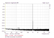
Second benefit of local NFB around VAS is VAS output resistance decreasing , so it is than more resistant to nonlinear load (output stage input impedance). Try to measure whole amp without output load , with VAS resitive loaded/ unloaded. It is not difficult to reach result as in attached picture (output 28V RMS, no output load). With 8ohm load it will increase to about 3ppm.
Attachments
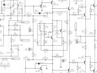
You clearly you did not look at the circuit diagram. The VAS clamp diode is BAV21.
The MUR140 are the flywheel diodes connected across the output devices.
Your plot is not of a power amp in a chassis with a normal PSU.
You also need to put a load onto it.
As I already stated, you can come this amp for MC which is what you are describing in your post.
The MUR140 are the flywheel diodes connected across the output devices.
Your plot is not of a power amp in a chassis with a normal PSU.
You also need to put a load onto it.
As I already stated, you can come this amp for MC which is what you are describing in your post.
Last edited:
Member
Joined 2009
Paid Member
Resistor loading may "throw" away gain, but even myself I have found it to "sound" better at the vas stage, so I would agree with Bonsai on this. In generL I take a build first, size it up, and once I feel it sounds great, then measure it. I find a lot more true groundwork gets done this way, after all it is the practical experience that truly means more. I truly like reading the threads of people who build it, then debate the merits not only using simulation and testing but also applying a description of the sound, if only audio were cut and dry huh? 😛
Colin
Given that low level of 2nd harmonic are reported to be nearly inaudible I wonder if the sonic impact of resistive loading is unrelated to the 2nd. I've found that the compensation of the VAS has a profound impact on the sonics for simple circuits - my clone of the AKSA amplifier was my first experience of how the sound changes with adjustments to Cdom and tuning Cdom 'by ear' was the easiest way to get the optimal value. Having said that, I don't have any distortion analyzing equipment in my 'lab' so the 'tune by ear' was all I could do.
I did..You clearly you did not look at the circuit diagram. The VAS clamp diode is BAV21.
http://hifisonix.com/wordpress/wp-content/uploads/2011/03/e-Amp-Circuit-Diagram.bmp
D10, D11= MUR140?
It is "normal" VFA with TMC , whole power amp (2x210W/4R) , no simulation, dualmono construction in a chassis with normal PSU (2x 300VA toroids), without output load , 28V RMS output. With 8R load, for various power it is here.Your plot is not of a power amp in a chassis with a normal PSU.
Last edited:
I don't know where your link is going - I cannot follow it. Attached is the circuit from the write up (v2.03). D10 and D11are BAV21.
You need to look at your plots driving a load.
Even without driving a load, the results you show extraordinarily good. You are saying your PSRR is circa 130 dB. By way of an example, with 1V ripple on the supply (nothing unusual) you are at less than 500 nV on the output. 100-200 uV of PSU noise on the output driving a load at 1 kHz is good.
Have you tried to see if you can lower your second harmonic by loading the VAS on your amp?
Attachments
Last edited:
Ovation e-Amp: A 180 Watt Class AB VFA Featuring Ultra Low DistortionI don't know where your link is going
Performance with output loaded is here . Plots are scaled in dBV, but voltage dividers are used (in order to keep input level for soundcard near 0dBV, where soundcard distortion is minimal) . So 0dBV always refers to fundamental level. So plot for 28V RMS is relative to 28V. It should be for clarity scaled in dBr, but it is impossible with ARTA software. And without output load (minimal current consumption) here is no reason for 1V ripple. Plots are real, measured performance.You need to look at your plots driving a load.
It is quite simple amp, simple cascoded LTP, with current mirror load , Hawksford cascode VAS with "beta enhancer" and current source as load, tripple EF output, TMC compensation, balanced input. I do not know, if it is extraordinarily good.. But it is real performance, achievable if one follows known rules.
Any aditional load from VAS output to ground increased distortions.Have you tried to see if you can lower your second harmonic by loading the VAS on your amp?
Last edited:
Bv i want to find that post which you link to "Performance with output loaded is here"
But the link just takes me back to the same post above.
Maybe some browser problem but can you give us the thread title and the post number ?
But the link just takes me back to the same post above.
Maybe some browser problem but can you give us the thread title and the post number ?
It is post #646 in this thread. Spectra for 100mW, 1W, 10W, 100W output power, 8R/1kHz. Bipolar, class B, 3EF output stage.
Last edited:
That is an old circuit. I will need to update the page but cannot do it from China.
Have you published your design?
Have you published your design?
No, but it is very close to "blameless" topology, with some improvements, like Hawksford cascode, TMC, focus on PSRR, etc...Have you published your design?
Because this amp is commercial product (small series production), still in production for our local market. But according all that I wrote here, You can draw schematic diagram.. 😉
It being his schematic, I was hoping he would point out any known asymmetry.
😎
NPN and PNP devices have different characteristics and transfer curves, thus unless both are matched including compensation for supply voltage, temperature etc, the symmetrical circuit can be also viewed as asymmetrical. Theres also environmental noises/ ambiance I guess at the end of the day what matters is...does it give you pleasure😎
NPN and PNP devices have different characteristics and transfer curves, thus unless both are matched including compensation for supply voltage, temperature etc, the symmetrical circuit can be also viewed as asymmetrical. Theres also environmental noises/ ambiance I guess at the end of the day what matters is...does it give you pleasure😎
I would dare to add at the end of the day is what allows you to feel closer to the music, like removing a layer of haze yet presenting in such a way that makes you want to listen to more music. That is the art of audio design for a music afficiandos 🙂
Colin
The loop gain on the e-Amp is flat to 40 kHz jcx.
When I put the VAS loading jumper in,my can see the 2nd harmonic do down and the THDcreading also goes down.
If someone is designing for single or sub single digit PPM, it is useful to remember.
28 to 20 ppm is about a 25 % reduction in distortion. That's significant.
But, in the context of a measurement residual floor of 14 ppm, it might not be 'measurement significant'. It's hard to measure closer than a handful of dB from residual and have any confidence in the numbers at all. There could be cancellations taking place that result in lower or higher reading magnitudes that are caused by lower or higher absolute distortion magnitudes canceling with the residual in an additive or subtractive manner.
It's depressing, but IIRC, a measurement has to be 10dB or so worse than residual to have full confidence in it. Of course, there are some ways to honestly cheat this, but 20 ppm vs. 14 ppm is a little close for comfort, and calls into question whether 28 ppm really did go to 20 ppm or not.
- Home
- Amplifiers
- Solid State
- Global Feedback - A huge benefit for audio