Some measurements before my mod.
Well, INMO this measurement shows hardly not a reference DAC..😕
May you provide interface (WDM /ASIO or...), sample rate and bits size used on your measurement. And just invite you to measure same thing using my Analyzer 😀
Specially the 19 to 20 kHz attenuation and also high IM content.
Hp
B&W_arthur,
Your FFT output spectrum measurements are basically correct (and so the IMD). I also got this sort of result in my audio output FFT measurements. As soon as I return to my "laboratory" I post my FFT readings if you want. And my "gig" measures less than 0.0005% THD from some Sigma-Delta DACs.
I also realized that these high order harmonics tend to disappear with weaker signals. These harmonics must be due to differences in internal resistance between the groups of shift registers (or the R-2R resistors, or both), generating a small non-monotonic region in the signal (if this also is not a small glitch problem at the output ).
I've repaired a interesting DAC from Krell, the Reference 64 (only an elcap trouble). Very interesting, with a dedicated 64x oversampling, ending in a PCM64 DAC chip operating at more than 2MHz, just like the DAM. But Krell has MSB and LSB trimmers, and a de-glitcher circuit in order to eliminate these artifacts in output waveform.
As the DAM artifacts are rather low in level, I can not tell if this infuence negatively the sound. For perfect measuring we need an Sigma-Delta DAC...
On another subject, the measurement of 4V lines, I realized in practice the 4V supply need to have a very low output impedance to not worsen the spectrum in output, testing with resistors in series with the 4V output. Therefore the use open loop sources will be a challenge to keep the line 4V without noise (maybe 500mA into an BJT follower). With only 1 ohm "internal impedance" from 4V line, the shift registers supply becomes an mess with high level "bass" interference, since I have used "only" 470µF of capacitance in the tests (try t measure the 4V line with 50Hz signal and high internal R supply). To maintain the 4V line under low impedance with opamps, perhaps the best would be to use an opamp with adjustable compensation, in order to adjust the bandwidth of the opamp vs the line and eliminate the peaking in the output. Or use various caps with different capacitance and ESR/ESL.
Last edited:
HpW, thanks for the comment.
It would be great if you point out to me which performance indicators look bad to you.
In case, please feel free to shed light on ways for improvement/modification.
Or, you can share your measurement with members here.
BTW, it seems that there is no standard way of using ARTA, specifically FFT in this thread.
Some members use FFT without playing any signal, others using different windows or FFT sizes as well as different fs...
DIYBras, I am looking forwards to your input and ideas.
Yes, you are right.
The THD are some what magnitude dependent.
That's why you see FFT @ -90 / -120 dBFS by Totaldac.
I am wondering if there are some frequency dependent artefacts...
My progress is sluggish...
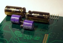
I only added caps suggested by these guys (courtesy of hifiduino and InMotion):
http://www.diyaudio.com/forums/vend...magnitude-24-bit-384-khz-321.html#post4409607
It would be great if you point out to me which performance indicators look bad to you.
In case, please feel free to shed light on ways for improvement/modification.
Or, you can share your measurement with members here.
BTW, it seems that there is no standard way of using ARTA, specifically FFT in this thread.
Some members use FFT without playing any signal, others using different windows or FFT sizes as well as different fs...
DIYBras, I am looking forwards to your input and ideas.
Yes, you are right.
The THD are some what magnitude dependent.
That's why you see FFT @ -90 / -120 dBFS by Totaldac.
I am wondering if there are some frequency dependent artefacts...
My progress is sluggish...
I only added caps suggested by these guys (courtesy of hifiduino and InMotion):
http://www.diyaudio.com/forums/vend...magnitude-24-bit-384-khz-321.html#post4409607
Attachments
Has anybody tried to shield/cover the resistor banks with copper foil or similar?
That rather huge and sensitive open area might pick up this or that EMI/RFI/interference,,,
Just an idea.
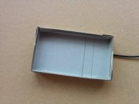
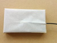
Assembled a small box, made of cardboard, stacked with emi textile and sandwich paper 😛 for isolation. Soldered a cable (the textile contsists mostly of metal alloy) on top. Then used double-faced adhesive tape in the corners to fix near the resistor array and connected the cable to the earth groundig of the alloy housing.
I cannot say that there is an real advantage, but I'm too lazy to switch back and fourth. Maybe the hammond housing does the job well.
----------------------------------------------------------------------------------------------------------------------
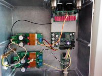
Actual system: DAM1021 0,05%, DIYINHK TPS7A4700 power, 4 OSCON 330uF/6.3V capacitors 4V reference, 1 OSCON 330uF/6.3V capacitor oscillator supply, EMI shielding of resistor array, DRV134 stacked on single ended output
Attachments
I have to qualify my last post: Changing the emi box back and forth shows that there is a light curtain pulled from the scene - very nice. Will not go back.
----------------------------------------------------------------------------------------------------------------------
Actual system: NewNos Filter, Firmware 0.9, DAM1021 0,05%, DIYINHK TPS7A4700 power, 4 OSCON 330uF/6.3V capacitors 4V reference, 1 OSCON 330uF/6.3V capacitor oscillator supply, EMI shielding of resistor array, DRV134 stacked on single ended output
Measurement After the first mod
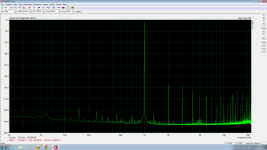
A simple measurement after the first mod.
For the PSU, I changed from Salas Shunt to an Talema transformer.
The noise floor goes down much, yet the harmonics distortion is "high" relatively.
Yes, it sound more dynamic.
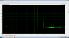
For the sake of reference, a measurement of Subbu Dac V3 is attached.
The harmonics distortion control is much better in Subbu Dac V3
although I love the Dam1021 sound much better.
Bad news, after putting 4 x 470u FM caps to Dam1021 buffer,
the Vref went wrong. It went to 0V. Thus, the mod process need to be stopped here.
A simple measurement after the first mod.
For the PSU, I changed from Salas Shunt to an Talema transformer.
The noise floor goes down much, yet the harmonics distortion is "high" relatively.
Yes, it sound more dynamic.
For the sake of reference, a measurement of Subbu Dac V3 is attached.
The harmonics distortion control is much better in Subbu Dac V3
although I love the Dam1021 sound much better.
Bad news, after putting 4 x 470u FM caps to Dam1021 buffer,
the Vref went wrong. It went to 0V. Thus, the mod process need to be stopped here.
Attachments
Let me get this straight. You changed from Salas shunt (dc in) to a Talema trannie (ac) in and achieved better results? Or was it the other way around?
I have to qualify my last post: Changing the emi box back and forth shows that there is a light curtain pulled from the scene - very nice. Will not go back.
----------------------------------------------------------------------------------------------------------------------
Actual system: NewNos Filter, Firmware 0.9, DAM1021 0,05%, DIYINHK TPS7A4700 power, 4 OSCON 330uF/6.3V capacitors 4V reference, 1 OSCON 330uF/6.3V capacitor oscillator supply, EMI shielding of resistor array, DRV134 stacked on single ended output
Thx for letting us know. Kind of expected exactly this result.
Many (most?) R2R ladders are put into modules. Modules (filled with stuff like casting resin) makes it easy to fight radiation, vibration, temperature, humidity issues.
On the long run Soekris might consider modules. Talking about modules.
If Soekris considers further product maintenance it would be nice to have the active
output stage attached as modules. Those who run passive-out wouldn't have to desolder
the active part anymore.
Another idea hit my mind. If modules would be considered , a stacking option would be nice too.
That potentially lowers the output impedance etc.
The Metrum Pavane might be a good example for all this.
Just thinking out load. 😉
Let me get this straight. You changed from Salas shunt (dc in) to a Talema trannie (ac) in and achieved better results? Or was it the other way around?
yes. the trannie gives lower noise in these tests.
my friend suspects that there are some fuzziness of the shunt.
sometimes we manage to get lower noise floor, sometimes not.
btw, i have no choice now. during the mod, i burned a shunt and the 4v ref.
i cannot do more comparison at the moment.
soundcheck, the idea of making module is good.
but pavane is not a good example.
the dam1021 has much superior spec.
but pavane is not a good example.
the dam1021 has much superior spec.
soundcheck, the idea of making module is good.
but pavane is not a good example.
the dam1021 has much superior spec.
may tell which spec of dam is superior than pavane?
HpW, thanks for the comment.
It would be great if you point out to me which performance indicators look bad to you.
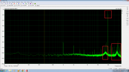
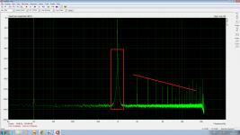
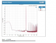
Arthur, OK, my indications are in red ..
first comment to 19/20kHz:
- 19/20 kHz have not the same level, may check your measurement and increase the sample rate
- some oscillation occurs... may look at http://www.diyaudio.com/forums/digital-line-level/269776-filter-brewing-soekris-r2r-125.html#post4414763
second comment on hum-less:
- spectrum content looks like as a square wave 😱
- may increase also the sample size from 32k to larger and use a better performing FFT Window as the Kaiser 7 😀
BTW: I do not own any DAM, loved too, but the issues 😱
and everybody is invited to measure using my evaluation analyzer 🙄
Hp
Attachments
BTW: I do not own any DAM, loved too, but the issues 😱
and everybody is invited to measure using my evaluation analyzer 🙄
Hp
A DAM is cheaper than a license of your software, so the most cost efficient solution would be you buy a DAM 😀
Moreover your software has a major flaw, it only works with Windows 😉😉😉
A DAM is cheaper than a license of your software, so the most cost efficient solution would be you buy a DAM 😀
Moreover your software has a major flaw, it only works with Windows 😉😉😉
All true 😀, I am working on it since 1995 (with man years) and could tell you that there is more engineering done (and continuously) .. and I know all are willing to pay for HW and not for SW 😀
The MS Windows argument ... once you have to start on a platform and your development platform do not put you lost in the dark 😱
Hp
Assembled a small box, made of cardboard, stacked with emi textile and sandwich paper 😛 for isolation. Soldered a cable (the textile contsists mostly of metal alloy) on top. Then used double-faced adhesive tape in the corners to fix near the resistor array and connected the cable to the earth groundig of the alloy housing.
I cannot say that there is an real advantage, but I'm too lazy to switch back and fourth. Maybe the hammond housing does the job well.
Great idea to shield the resistors. It may work better if you manage to connect the box directly to the DAM ground plane in as many points as possible along the perimeter. Ideally, to make a Faraday cage, it should have uninterrupted contact with DAM ground plane along the entire box perimeter, but that is unfortunately not possible with the existing board layout.
Connecting it at only one point by a long wire makes an antenna, not an EMI shield.
Hi Soekris,*
****************** NOW TAKING ORDERS ********************
I have been working on a little side project, now it's time to present it for everybody here....
It's a DAC module based on a discrete R-2R sign magnitude DAC design, with FPGA based reclocking and custom digital filters, < 1 ps jitter clock generator, with 28 bit resolution so there is headroom, oversampling up to maybe 3.072 Mhz. Up to 24 bit / 384 Khz input from SPDIF, I2S and USB (via USB to I2S interface board), with isolation on the I2S interface. The board will be very flexible, with digital volume control and filter parameters that can be downloaded, a possibility is also to add digital crossover filters, but that will probably not be ready for first production lots, although the board is firmware upgradable over a simple serial connection.
The basis R-2R network has an output voltage of 1.4V RMS and output impedance of 625 ohm and can therefore drive a lot of things directly.... There is also onboard balanced output drivers that can drive high impedance (>= 300 ohm) headphones directly. The power supply is also onboard, just add a 5W toroid transformer.
It is a small mostly surface mount PCB, and yes, I have working prototypes, see below.... But it's not really something for home assembly, with the FPGA in BGA package and 600 pcs SMT parts.... So yes, if there is enough interest it will go into real production, with sales though two existing online shops in US and EU.
Performance of first prototypes using 0.05% resistors is better than expected, see 1 Khz -1 db and -60 db FFT plots. I believe that the sound quality will be the absolute best, better than any Delta Sigma DAC, in class with discrete DAC's from totaldac and msb technology. And for way way less cost 🙂
Update on May 10, 2015:
We're out of stock of the 0.01% and 0.05% versions, we still have good stock of the 0.02% version.
Boards from next production run will be available early August 2015.
Final pricing is:
0.05% resistor version USD 170 / EUR 137
0.02% resistor version USD 235 / EUR 190
0.01% resistor version USD 325 / EUR 263
Shipping cost and any sales tax and/or other local taxes to be added.
They are available to order though two existing webshop:
dam1021 Product Range - *NEW* - Audio Products - Products for American and Asia markets.
Soekris Europe » for EU and European markets.
The main website for product and technical information is:
Soekris Engineering, Inc. | Single Board Communication Computers
See also post #901 http://www.diyaudio.com/forums/vend...-magnitude-24-bit-384-khz-91.html#post4197094 for a quick drawing with connections.
And post #1108 http://www.diyaudio.com/forums/vend...magnitude-24-bit-384-khz-111.html#post4202602 for SPDIF interface drawing.
And great info here https://hifiduino.wordpress.com/2015/01/30/building-soekris-r-2r-dac/
Post #1486 http://www.diyaudio.com/forums/vend...magnitude-24-bit-384-khz-149.html#post4216998 with filter tools.
Anybody can now order the dam1021 R-2R DAC board from the two webshops.
One year after the ambicious target - "I believe that the sound quality will be the absolute best, better than any Delta Sigma DAC, in class with discrete DAC's from totaldac and msb technology" - what do you think personally, how much this goal was achieved?
Arthur, OK, my indications are in red ..
first comment to 19/20kHz:
- 19/20 kHz have not the same level, may check your measurement and increase the sample rate
- some oscillation occurs... may look at http://www.diyaudio.com/forums/digital-line-level/269776-filter-brewing-soekris-r2r-125.html#post4414763
second comment on hum-less:
- spectrum content looks like as a square wave 😱
- may increase also the sample size from 32k to larger and use a better performing FFT Window as the Kaiser 7 😀
BTW: I do not own any DAM, loved too, but the issues 😱
and everybody is invited to measure using my evaluation analyzer 🙄
Hp
Thank you for your comments.
I would suggest you buy a Dam board AND use the ARTA to run tests rather than making "educated guess".
I have made my position about FFT clearly in my previous post. There are many tricks to make a FFT looks good. I am not going to repeat my points again. I suggest you reread it.
If you find my explanation not convincing, please refer to the attached FFT made with an Audio Precision Apx 515 in May ( in fact, you can search my previous post to find a more detailed Audio Precision measurement of Dam1021 in late May).
Do you think that Audio Precision APx515 is using square wave for FFT?
IMHO, Soekris has done a great job in designing the DAC, in particular the noise control (the very low noise floor even by plugging an transformer) and how it sounds. Of course, we are looking forwards to his firmware update/grade and other improvement of the design. Specifically, I want to have a dual mono balanced implementation of the DAM1021 DAC.
My only dissatisfaction about the DAC is its high THD (although I doubt whether people can hear harmonic distortion at -8xdB level). In comparison, an old PCM170x DAC (designed by my friend) has lower distortion than the DAM1021. And, its THD compared badly against the Subbu DAC V3's (see the figure posted several days ago).
Attachments
Last edited:
A simple measurement after the first mod.
For the PSU, I changed from Salas Shunt to an Talema transformer.
The noise floor goes down much, yet the harmonics distortion is "high" relatively.
Yes, it sound more dynamic.
For the sake of reference, a measurement of Subbu Dac V3 is attached.
The harmonics distortion control is much better in Subbu Dac V3
although I love the Dam1021 sound much better.
Bad news, after putting 4 x 470u FM caps to Dam1021 buffer,
the Vref went wrong. It went to 0V. Thus, the mod process need to be stopped here.
Thanks for including measurements of our V3 compared to a modified/improved DAM1021. I think the comparison is somewhat off as DAM1021 is way more expensive (and R2R) but I would not hesitate to do it myself too if I had the DAM1021. Still the Subbu V3 does perform quite good when taking price and simplicity in consideration. To be honest I would choose the V3 if only measurements are concerned 🙂 (just joking, I would never advertise my own stuff
 ). Which PSU did you use on the V3 ? Were both DACs measured using SPDIF ?
Last edited:
On FFT by ARTA
1. Members posted FFT in this thread. However, few generated FFTs with 1kHz signal.
In addition, at what was the 1kHz signal played? at 0dBFS? -3dBFS? or, -60dBFS?
There is no consistent way of making measurement, FFT can't be compared effectively.
If you use a lower level signal, you get better looking FFT. If one does not play any signal, you get a MUCH lower noise floor. Personally, I use -3dBFS and -60dBFS at 997kHz. Yes, 997kHz. Some software produce fuzzy looking FFT with 1kHz. I found TotalDAC reporting 1kHz signal played at -110dBFS absurd. Stereophiles used -90dBFS for measuring MSB Diamond DAC...
2. when you make the FFT, what fs is used? Personally, I only have 44.1kHz music files,
I use primarily 44.1kHz. Since I find the Dam1021 has much high frequency noise near the 30~40kHz region, I also use 96kHz to check if there is improvement at this region after modification.
3. FFT size. I don't know if there is a standard value. The larger value the FFT looks better.
4. For the sake of comparison, I primarily use Kaiser7 as most members use this window. However, I also use Hanning because Seokris used Hanning in the first post.
5. Members using different soundcards with ARTA. I doubt whether the results are consistent and repeatable.
Last edited:
Personally, can't say much about this dac as I bought 4 more than 6 months ago under the assumption it would be usable in an active 4 way system and have yet to see any documentation instructing the user in this implementation. Thus, I am still waiting...and wondering if I made a poor decision...
- Home
- Vendor's Bazaar
- Reference DAC Module - Discrete R-2R Sign Magnitude 24 bit 384 KHz