I don't use MOSFET, it is much harder to have close match of Vgs as they vary. It's a different ball game, apply and orange.
Mosfets are much less critical when it comes to matching, since Id=f(Vgs) is parabolic, while for bipolars Ic=f(Vbe) is exponential. Hence, mosfets are much less prone to current hogging and thermal runaway.
Absolutely wrong, I'm afraid.
As I believe I said before, I have used 0R1 as standard for a couple of decades, in amplifiers in serious mass production. Thermal stability has never been an issue.
As it happens I have a four-output-pair amplifier under detailed measurement at the moment. Re tolerance is 5%. No thermal stability issues whatsoever. The bias generator is naturally mounted on the top of one of the output devices.
A better question is if 0R05 resistors are practical politics. Probably it would be necessary to take a hard look at PCB track resistances. Two-ounce copper would help there, but I always use it for power amp PCBs anyway.
Another good question is if 5% is close enough to prevent the generation of distortion because the gains are slightly different in the +ve and -ve directions. I have done some work on this...
Douglas, I have built many amplifiers and done hundreds of sims. Without matching OPS devices and using 0.22 ohm Re's I easily get 10 % variation in Ie.Re with 4R7 base stopper resistors as measured across the Re's of two pairs of output devices. If you are saying it's better than this across the same or more output pairs with 0.1 ohm devices please share your results. The transistors in my case were not matched, and the Re's are spec'd at 5%.
Last edited:
Douglas, I have built many amplifiers and done hundreds of sims. Without matching OPS devices and using 0.22 ohm Re's I easily get 10 % variation in Ib.Re with 4R7 base stopper resistors as measured across two pairs of output devices. If you are saying it's better than this across the same or more output pairs with 0.1 ohm devices please share your results. The transistors in my vase were not matched, and the Re's are spec'd at 5%.
Do you mean Ie or really Ib? You measure across the Re or the base stop?
You take the words right out of my mouth. I still have 0.22ohm on the board to power up. I match transistors first, power up and measure the result first. If I get 10% variation of Ie, I won't even attempt to lower the Re. If it looks very close, then I want to parallel resistors to lower the Re. But short of that, I won't even try. I am very close to doing that. I finally have all the stuffs for testing including the QA400 distortion analyzer.
I remember you said you bias over Oliver's condition, maybe you proved the point AndrewT talked about that one needs to bias over 26mV across Re to compensate for the higher temperature. But I thought you mentioned you bias almost 1.8 times the Oliver's condition, that's like over 40mV across the Re instead of about 32mV.
As I remarked in one or the articles on my website, we have replaced the nonsense of subjectivism with the tyranny of objectivism. If distortion figures that are orders of magnitude below the threshold of human perception are your design goal, then you are destined to produce over complicated designs that add no value to the listening experience.
To write off CFA because you believe it cannot achieve the distortion performance of VFA is a nonsense. I've shown designs that deliver 1.2 PPM at 400 W out on this forum at 20 KHz. However, I am not going to build this because it will sound no better than a simpler design delivering the same power at 100 ppm.
To write off CFA because you believe it cannot achieve the distortion performance of VFA is a nonsense. I've shown designs that deliver 1.2 PPM at 400 W out on this forum at 20 KHz. However, I am not going to build this because it will sound no better than a simpler design delivering the same power at 100 ppm.
I run my OPS at circa 120 mA vs the ideal of 78 mA per pair simply because to my ears it sounds more euphonic. Yes, on sims the distortion is a little bit higher, but I am ok with this..The designs are engineered for lowest distortion then tweaked for aural satisfaction. It's like the difference between a brandy at 9 degrees C and one at 24 deg C. Or, an 18 year old single malt versus an 8 year old blend - you know, the ones the some like to mix with coke . . .
Oh the joy of it!
Oh the joy of it!
Last edited:
As I remarked in one or the articles on my website, we have replaced the nonsense of subjectivism with the tyranny of objectivism. If distortion figures that are orders of magnitude below the threshold of human perception are your design goal, then you are destined to produce over complicated designs that add no value to the listening experience.
To write off CFA because you believe it cannot achieve the distortion performance of VFA is a nonsense. I've shown designs that deliver 1.2 PPM at 400 W out on this forum at 20 KHz. However, I am not going to build this because it will sound no better than a simpler design delivering the same power at 100 ppm.
Ha ha, there goes to show there is no consensus even between experts. I have a CFA and Hiraga on my radar after this. I think CFA makes a lot of sense.
I've heard of amplifiers (both linear and class D) compensated up to the 5th order, but I have never seen a schematic.
The Hypex NCore series have 5th order control loops. One of the difficulties with high-order loops is conditional stability and how to maintain good amplifier behaviour during/after clipping. One of Hypex’s patents is:
Patent US20110068864 - Self oscillating class D amplification device - Google Patents
See also:
The Design of an Analogue Class-D Audio Amplifier Using Z-Domain Methods
Which was a project supervised by Bruno Putzeys (the guy behind the NCore amplifiers) and details the design of a Class-D amplifier with high-order control loop and fixed-frequency modulation, as apposed to the variable-frequency self-oscillating modulation of the NCore.
The Hypex NCore series have 5th order control loops. One of the difficulties with high-order loops is conditional stability and how to maintain good amplifier behaviour during/after clipping.
Thanks, that's the one I've heard about.
I would add sensitivity to the list of high order compensation possible pitfalls.
Absolutely wrong, I'm afraid.
As I believe I said before, I have used 0R1 as standard for a couple of decades, in amplifiers in serious mass production. Thermal stability has never been an issue.
You are a very lucky man. You miss the point: going to 0.1 ohms is simply not worth it in an EF output stage.
Cheers,
Bob
It's just not good enough to say "I said so that 0.1ohm is safe". It just does not make sense. Even with all my hand picking devices, I start with 0.22ohm and see what kind of voltage across Re. If it is more than 3 or 4mV variation, I won't even going to try to lower the Re.You are a very lucky man. You miss the point: going to 0.1 ohms is simply not worth it in an EF output stage.
Cheers,
Bob
Once and forever, since this is coming again, and again, and then again... Given a phase margin, an ULGF, and a compensation method order, a CFA circuit topology does NOT provide more loop gain than what you could get with a standard VFA. To understand this, before going to the Lurie stability or the Bode integrals, there is an almost trivial justification: whatever Mr. Zan is going to mumble and moan, audio circuit topologies are still of the minimum phase breed. As such the gain and phase are NOT independent, therefore pushing up the loop gain, pushes down the phase margin, no exceptions (or free lunch, if you prefer). Changing the compensation order is the only way to break this rule, by adding N poles and N-1 zeroes in the unity circle (N=1 Miller compensation, N=2 TPC or TMC, N=3 Cherry NDFL compensation). I've heard of amplifiers (both linear and class D) compensated up to the 5th order, but I have never seen a schematic. The CFA circuit topology has other interesting properties, none of which really matters for audio.
Your example with 80dB loop gain @ 20KHz is either a typo, or you are talking a different and strange Bode language. Even if a two pole type compensation is involved, such an amplifier would have a ULGF higher (I would estimate some 8-10 MHz) that what could be of any practical importance for a power amplifiers (with the power stage limiting the bandwidth).
Yes, the compensation order is the reason, go to the 200W CFA MOSFET thread and take a look.
CFA indeed does not provide 'more loop gain'. In simple classic versions, it is very fast (ie small signal rise fall times) and slew rates are also very high. Further, because it only has 2 poles and lower loop gains, for a given ULGF, the concomitant phase margin is greater. Raise the loop gain eg by using a Darlington TIS and the amplifier behavior in terms of ULGF phase margin looks more like that of a VFA. Further, if high loop gains are your thing, CFA's can deliver the goods in terms of distortion just as well as a VFA (single digit ppm at 20 KHz at rated power). It goes without saying that the PSRR is lower than VFA to the tune of 20-30 dB.
However, the real attraction of CFA's is their simplicity, ease of compensation along with the fact that they are fast. If you are sensible about distortion objectives, they are a very interesting option in my book.
However, the real attraction of CFA's is their simplicity, ease of compensation along with the fact that they are fast. If you are sensible about distortion objectives, they are a very interesting option in my book.
Last edited:
CFA indeed does not provide 'more loop gain'. In simple classic versions, it is very fast (ie small signal rise fall times) and slew rates are also very high. Further, because it only has 2 poles and lower loop gains, for a given ULGF, the concomitant phase margin is greater. Raise the loop gain eg by using a Darlington TIS and the amplifier behavior in terms of ULGF phase margin looks more like that of a VFA. Further, if high loop gains are your thing, CFA's can deliver the goods in terms of distortion just as well as a VFA (single digit ppm at 20 KHz at rated power). It goes without saying that the PSRR is lower than VFA to the tune of 20-30 dB.
However, the real attraction of CFA's is their simplicity, ease of compensation along with the fact that they are fast. If you are sensible about distortion objectives, they are a very interesting option in my book.
I still don't quite totally understand the CFA. I am surprised that the loop gain is not that high. But the important question is whether it has higher loop gain at 20KHz than the VFA.
I think at low frequency, the distortion is low because of the loop gain, it's really not as critical. It's the higher frequency loop gain that is important. I posted before that if you want good noise reduction, you have to have loop gain of like 40dB or more at that frequency. For normal VFA that the -3dB frequency is say 400KHz(very high already). the loop gain at 20KHz is only 26dB or 20 if it is dominant pole compensation. that's not a lot of loop gain. If the CFA can do better than 26dB loop gain at 20KHz, CFA will win out. 26dB is very low loop gain!!!
...Just for the record, I do have a copy of Bode's book...
I frequently recommend this book, maybe I am repetitious but it's hard to overstate how fundamental it is.
I have read that the later copies have some addenda and I would love to check this.
What year or edition/print run is your copy?
Best wishes
David
CFA indeed does not provide 'more loop gain'. In simple classic versions, it is very fast (ie small signal rise fall times) and slew rates are also very high. Further, because it only has 2 poles and lower loop gains, for a given ULGF, the concomitant phase margin is greater. Raise the loop gain eg by using a Darlington TIS and the amplifier behavior in terms of ULGF phase margin looks more like that of a VFA. Further, if high loop gains are your thing, CFA's can deliver the goods in terms of distortion just as well as a VFA (single digit ppm at 20 KHz at rated power). It goes without saying that the PSRR is lower than VFA to the tune of 20-30 dB.
However, the real attraction of CFA's is their simplicity, ease of compensation along with the fact that they are fast. If you are sensible about distortion objectives, they are a very interesting option in my book.
This is LG of my 200W CFA mosfet and it is nothing like VFA. I never succeeded to have more than 60, 65 dB of the loop gain at 20 kHz with the VFA.
Attachments
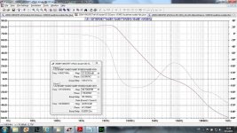
Phasemargin does not look to healthy, less than 10 degrees at 200 Khz.
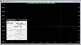
heres my VFA. bit more heathy and still ppm distortion at 20 Khz 26V-pp
"Total Harmonic Distortion: 0.002709%"
heres my VFA. bit more heathy and still ppm distortion at 20 Khz 26V-pp
"Total Harmonic Distortion: 0.002709%"
Attachments
Last edited:
Phasemargin does not look to healthy, less than 10 degrees at 200 Khz.
heres my VFA. bit more heathy and still ppm distortion ad 20 Khz 26V-pp
"Total Harmonic Distortion: 0.002709%"
What are you talking about. Phase margin for this amp is very healthy with 87 degree and Gain margin is exceptional, 40 dB. That drop at 200 kHz is standard behavior of two pole compensation, nothing to worry about.
Your compensation is not optimal as I can read from the Bode plot.
This is LG of my 200W CFA mosfet and it is nothing like VFA. I never succeeded to have more than 60, 65 dB of the loop gain at 20 kHz with the VFA.
Probably because you never tried (or never succeeded to implement) a double pole and a zero close to the ULGF (like you did in the simulation of your CFA). That is a pretty trivial exercise, however it would be as much dangerous as in yours, from a stability perspective.
Double poles have high sensitivity (that is, the ULGF will move significantly with component tolerances, bias conditions, signal level, etc...). I have never seen double poles in anything but simple filters (like the Sallen-Key topology) and switching mode power supplies.
It would be interesting to simulate the same amp when the output approaches the rails, something you always avoided to show, by keeping a comfortable margin of 10-15V-20V. That's when the beast shows it's ugly head. It would also be interesting to see the clipping behaviour (when the loop gain collapses without much control, and the conditional stability may hit you).
I know you proudly built this amplifier and are trying to promote it by all means. Even if you hit the jackpot once, this doesn't mean this amp will survive the abuse that an audio amplifier should be prepared to face in day to day operation. I can show you a 100W mosfet power amplifier with an ULGF of 40MHz, that appears to be very stable in simulation. Which doesn't mean I am ever going to even try building it, not to mention trusting it enough to feed a pair of (borrowed, since I don't have any) expensive speakers.
I always adjust my compensation on the board. Spice is in that respect a rather coarse tool.
I have built many CFA's but have reverted to VFA, the base performance of CFA (drive, impact ans resolution) regardless of diamond front or not just doesn't cut it for me.
I have built many CFA's but have reverted to VFA, the base performance of CFA (drive, impact ans resolution) regardless of diamond front or not just doesn't cut it for me.
- Home
- Amplifiers
- Solid State
- Bob Cordell's Power amplifier book