Well, it's just "saturation" by definition. Coilcraft says Isat@10% Ldrop, Bourns at 20% Ldrop. Of course they slope a bit, the question is, will it be audible? (I'd guess, the Coilcrafts will do as well)
Quite possibly, yeah.
If the L is changing with the audio envelope, it causes the output filter Fc and Q to move around with the L, causing the high frequency response of the filter to dynamically change.
It isn't a huge stretch to imagine low frequency content effectively causing AM/PM modulation of high frequency content, causing IM distortion.
Well, there will also be compression in the audio drivers at higher volume. So even if the filters are not ring/modulate, there will be (alot) more distortion from the speakers itself. 😀
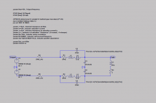
Constructing a simulations model for this atm.
Constructing a simulations model for this atm.

Btw, the Coilcraft's looking that good, because double-log chart in datasheet. 😀
From the simulation at full-scale output (PVCC) into 2R+47uH.
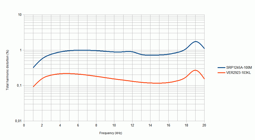
From the simulation at full-scale output (PVCC) into 2R+47uH.
Attachments
Last edited:
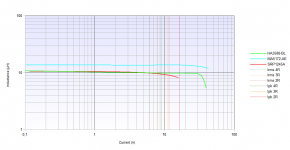
I think there will be quite a difference between Inductors using ferrite and those using some kind of iron powder like carbonyl. Compare the L vs current diagrams and you will see the difference. Ferrite shows a sharp saturation point, iron powder degenerates in a more smooth way. Actually I compare 10uH smd inductors in a stepup converter (3 amps ripple current at 250kHz) and found that carbonyl cores are less lossy than their ferrite counterparts.
Last edited:
So we have
carbonyl = soft saturation, less loss
ferrite = hard saturation, more loss
?
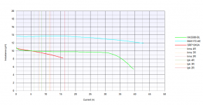
For the comparsion, lin vs log makes the "difference".
All 10uH inductors
Coilcraft HA3588-BL = AGP2923-103KL = VER2923-103KL
Coilcraft MA5172-AE - stated as 10uH, from the datasheet
Bourns SRP1245A
While Coilcraft prefers dual-log, Bourns do dual-lin.
carbonyl = soft saturation, less loss
ferrite = hard saturation, more loss
?
For the comparsion, lin vs log makes the "difference".
All 10uH inductors
Coilcraft HA3588-BL = AGP2923-103KL = VER2923-103KL
Coilcraft MA5172-AE - stated as 10uH, from the datasheet
Bourns SRP1245A
While Coilcraft prefers dual-log, Bourns do dual-lin.
Attachments
Last Spam for today..
It looks extremely good. What 3d app do you use?
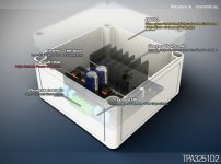
This is KiCAD VRML export with custom 3d-models in a HDR renderer + some postprocessing in Photoshop.
Blender, HDR Light Studio.

Blender, HDR Light Studio.
Hi doctormord, just wondering when will your design be up? I'm actually interested in this rather as it has more power. How long do you think it will be ready? I should be able to balanced it with twice the boards.
Well, my design's coming along. Nothing's committed to PCB yet, but I've got the schematic mostly put together. Some design notes:
Card can be powered off a single 24-36V supply. I'm using a LM25017 buck regulator IC to make 12V from the input voltage to power VDD/GVDD and the analog input stage, and a secondary winding on the buck inductor makes -12V for the analog input.
Analog input is a pair of instrumentation amplifiers made out of OPA2134s, providing "proper" differential inputs that'll behave nicely with both single-ended and differential input sources. There'll be jumpers or DIP switches to set the input gain. There'll be good input protection using diodes to clamp the inputs to protection rails.
I'll have a microcontroller handling startup/shutdown. I'll provide drive for a bicolor red/green LED displaying different states. LED off = amp off, green = amp running, amber = overtemperature warning, red = bad things.
Still figuring out heatsinking. Original plan was to mount the TPA bottom-side and bolt the card to a metal plate, but instead I'll mount the TPA topside with a bolt-on heatsink, and mount the small decoupling bottom-side instead so I can have it in close proximity to the TPA. Getting metal plates made in low quantities is way too expensive in low quantities, and the costs of screws/standoffs/etc adds up pretty quick too.
Bottom side decoupling for everything on PVCC won't be a good thing in my opinion. The Tpa is 1mm in height so caps will fit if you split the decoupling. Have a look for 0612 TDK low profile.
Well, my design's coming along. Nothing's committed to PCB yet, but I've got the schematic mostly put together. Some design notes:
and a secondary winding on the buck inductor makes -12V for the analog input.
I wonder how this works.

I'll fit whatever I can under the heatsink. The bigger 0805/1210 caps I use on PVCC/AVCC/etc will have to go bottom side, I don't think it's a huge issue.Bottom side decoupling for everything on PVCC won't be a good thing in my opinion. The Tpa is 1mm in height so caps will fit if you split the decoupling. Have a look for 0612 TDK low profile.
Opening up the bottom side for parts will probably also help with things like decoupling the audio input op-amps while maintaining a tight/clean layout.
We'll see, haven't begin PCB work yet.
- Home
- Amplifiers
- Class D
- TPA3251d2