😱😕
yes ,can't be magnified ........
I'm sorry if the image can not be enlarged,, open this link🙂🙁😛
https://anistardi.wordpress.com/2014/12/25/big-perkutut-amplifier/
Too small to see.
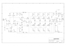
tes simulation here,,
Phase Margin = 86 degrees
Gain Margin = 12 dB
Slew Rate = 77V / μS
THD at 162W / 8Ohm, 1kHz -> 0.005081%
THD at 162W / 8Ohm, 20kHz -> 0.018084%
THD at 324W / 4ohm, 1kHz -> 0.008546%
THD at 324W / 4ohm, 20kHz -> 0.019794%
PSRR at 1kHz -> 107 dB
https://anistardi.wordpress.com/page/4/
Hello hajidian
greetings is the blameless 1200 watt a tested design
warm regards
Andrew
Hello hajidian
greetings is the blameless 1200 watt a tested design
warm regards
Andrew
this layout is not be tested,,https://anistardi.wordpress.com/page/4/
Hello hajidian
greetings is the blameless 1200 watt a tested design
warm regards
Andrew
best regards
Haji
Attachments

Ah, it's Bimo, an active member of this site. I knew it, because there is no solid state amplifier expert in my country 😀
It's a simulated distortion. There is NO way the real performance can reach that, with such bootstrapped LIN topology.
It's a simulated distortion. There is NO way the real performance can reach that, with such bootstrapped LIN topology.
yes I know it,, where you come from?Ah, it's Bimo, an active member of this site. I knew it, because there is no solid state amplifier expert in my country 😀
It's a simulated distortion. There is NO way the real performance can reach that, with such bootstrapped LIN topology.
Hi hajidian,
Yup, not that design. The distortion figures have waaaay too many figures after the decimal point. Readings are always noisy and you can't measure to that level of accuracy.
One very helpful improvement might be to regulate the power supply rails for the voltage amplifier stage. You will gain s/n ratio and freedom from the heavy currents of the output stage to affect the voltage amplifier stage. Break it at the 100 ohm resistor + diode point and feed the front end from there.
Your performance will depend greatly on how closely you match the input pairs (2SC1845) and how closely they are tied together to maintain the same temperature. There is no reason why it won't sound very good if you follow those points.
How hard are you going to run this amplifier? If you are going for high power, the drivers should be beefed up, or even make the output stage a triple. Amplifiers don't usually "scale up" to higher power without some more changes.
-Chris
Hi, this is my design 😀
I want to make amplifier as simple as possible and enough power. I choose double emitter follower because it simple but if use high power supply and low impedance load (below 4 Ohm), THD will be too high. So, this is my compromised.
You can not use it for 2 Ohm speaker, unless you change output stage to triple emitter follower and add more output transistors. It tested by one of my friend. In first version, the current for LED is too small then he increase power supply to +-70VDC. It stable and sound good according him 😎 The second version, I increase LED current. It should be stable for +-63VDC power supply.
Hi bimo,
What power levels are you hoping to run at? All I know is that with that many output transistors, the poor little 2SC4793 / 2SA1837 will die first during a current spike into the load. Some 4 ohm speakers have a nasty impedance curve.
What do you think about running the voltage amp stage from clean power (ie regulated)?
-Chris
what do you think about this amp.. can you give me any sugestion?Hi bimo,
What power levels are you hoping to run at? All I know is that with that many output transistors, the poor little 2SC4793 / 2SA1837 will die first during a current spike into the load. Some 4 ohm speakers have a nasty impedance curve.
What do you think about running the voltage amp stage from clean power (ie regulated)?
-Chris
regards

Last edited:
Hi hajidian,
The amplifier is a basically good design. I just had a couple of questions, that's all. I would let bimo answer first before deciding anything. Besides, we still don't know how much power you are wanting out of this amplifier.
-Chris
The amplifier is a basically good design. I just had a couple of questions, that's all. I would let bimo answer first before deciding anything. Besides, we still don't know how much power you are wanting out of this amplifier.
-Chris
i think 350 Watt at 4 ohm load,,, 😀Hi hajidian,
The amplifier is a basically good design. I just had a couple of questions, that's all. I would let bimo answer first before deciding anything. Besides, we still don't know how much power you are wanting out of this amplifier.
-Chris
Hi bimo,
What power levels are you hoping to run at? All I know is that with that many output transistors, the poor little 2SC4793 / 2SA1837 will die first during a current spike into the load. Some 4 ohm speakers have a nasty impedance curve.
What do you think about running the voltage amp stage from clean power (ie regulated)?
-Chris
2SC4793 / 2SA1837 capable to drive 350W/4 Ohm. For pure 2 Ohm load (non inductive) those driver transistors still within their SOA. But of course MJE15032/33 is better but expensive.
EF Triple, but that's just my recommendation.
-Chris
I already make simulation using triple 🙂 and make PCB layout, too. But I can not share it here. I adopt Mr. Hugh Dean (AKSA) design philosophies on this design. It will have H2 dominant but THD still reasonable low, and of course it have high slew rate 😎
2SC4793 / 2SA1837 capable to drive 350W/4 Ohm. For pure 2 Ohm load (non inductive) those driver transistors still within their SOA. But of course MJE15032/33 is better but expensive.
If using MJE15032/33, C lead must be increase to 10pF to maintain the phase margin.
Hi bimo,
Please say hello to Hugh for me.
I use the 2SC4793 and 2SA1837 myself. I have a bunch of them, but I would still use the heavier drivers for this project.
Cheers! -Chris
Please say hello to Hugh for me.
That is the road I would recommend. By comparison, how much more expensive would the ON Semi parts be. He is only making his own amplifier, so the difference in price on the entire project wouldn't be that much.If using MJE15032/33, C lead must be increase to 10pF to maintain the phase margin.
I use the 2SC4793 and 2SA1837 myself. I have a bunch of them, but I would still use the heavier drivers for this project.
Cheers! -Chris
- Status
- Not open for further replies.
- Home
- Amplifiers
- Solid State
- from DIY Indonesian Amplifier