The RCA to XLR connectors are just fine although not as elegant as the Rolls solution. Ordinarily a system has lots of spare volts to feed the amp, mismatched and all. I'd bet the shortcoming in final loudness is some basic wiring goof. (BTW, when you are working with the re-connecting, take care lest you put an immense signal into that big amp based on earlier levels.But now I have a new question to ask Artisan. The sound module has eight 1/4 inch RCA female output sockets. I want to use the XLR inputs on the Crown amps. So I bought color coded patch cables with RCA male plugs on one end and XLR males on the other end. Now I have to find out more on the output from these 1/4 inch jacks on the Artisan Sound Engine. I don't want to have to buy or use the $65 Rolls converter boxes for these channels when we are finally connected.
I'm working hard, but I'm still enjoying myself. 🙂
Bach On
Just bring in your HiFi from home. Some of my gear puts out 10 volts (even if some gear, like a CD player may peak at .7v). That, and almost anything from the Salvation Army (that has any HiFi aspirations, of course) will do fine for temporary use and the tone controls may provide some additional diagnostic benefits.
"Draft Stop" is a great temporary caulk. It is nothing like silicone. But it might be a great solution to your permanent installation too since it stays in place nice and firm until you yank the whole string off. (Works for driver gaskets too.)
Ben
The RCA to XLR connectors are just fine although not as elegant as the Rolls solution. Ordinarily a system has lots of spare volts to feed the amp, mismatched and all. I'd bet the shortcoming in final loudness is some basic wiring goof. (BTW, when you are working with the re-connecting, take care lest you put an immense signal into that big amp based on earlier levels.
The connection is not the problem. The impedance mismatch is the problem. Think 8 ohm capable amplifier being asked to drive 2 ohm loudspeakers.
There is not enough current. The rolls box solves the problem by being a dedicated pre-amplifer in series. The bass roll off is mitigated by the changing of the two capacitors as shown in the directions on Colos website.
Bach On if you need a little walk through on desoldering a capacitor from the printed circuit board please say so. But it is as easy as heating up one leg and pulling the leg up and away from the board. Only heat until you have melted the solder and get the work done quickly. Those cheap printed circuit boards do not like being heated up. The copper foil will lift on them if you abuse them with prolonged heat. Prolonged generally means more than 30 seconds.
Otherwise it is not a difficult job.
Solder wick is also your friend. http://www.amazon.com/MG-Chemicals-Series-Braid-Super/dp/B008UH393K
Helps you clean up the old solder very nicely.
https://www.youtube.com/watch?v=htrcZuK_ZsY
Um, not quite. Standard input impedance for "line input" is 10k ohms. Only phono input is standard at 48k.
The connection is not the problem. The impedance mismatch is the problem. Think 8 ohm capable amplifier being asked to drive 2 ohm loudspeakers.
There is not enough current. The rolls box solves the problem by being a dedicated pre-amplifer in series. The bass roll off is mitigated by the changing of the two capacitors as shown in the directions on Colos website.
It might just be my misunderstanding of the circuits, but your conception of the principles of electronics differs from mine.
Upstream of the amp output, only volts are worth fussing over. One hardly ever encounters units with anything but low output impedance or needing atypically high input impedance requirements.
About power an amp can ship to a speaker with unexpectedly low impedance, well, there can be concerns when the amp is pushed.
I'd be surprised if Bach On will be pumping more than a tiny fraction of the amp power. for testing or much more later on (unless he's really going for the Jaws effects). The power is needed for complex music waveforms with momentary stochastic peaks (esp. women's choirs).
Ben
Ben
I doubt if much/any signal etc gear these days requires high impedance inputs. Even cheap gear should have around 100 Ohms output impedance/resistance, so would have no problems seeing anywhere near a 10k input. Even if gear had 1k Ohms output impedance/resistance, it'd still be ok.
I'm not keeping up with the times I see.
Still does not explain the lack of drive on the Crown amplifier though.
And I have had quite a few clients that have had to get the old interface box.
Still does not explain the lack of drive on the Crown amplifier though.
And I have had quite a few clients that have had to get the old interface box.
Gain Structure for Home Theater: Getting the Most from Pro Audio Equipment in Your System - Home Theater Forum and Systems - HomeTheaterShack.com
I am getting rusty. I haven't done any audio electronics design in quite a while better part of 20 years. But the link above has a good in depth explanation of the why's wherefores and such as's.
I am getting rusty. I haven't done any audio electronics design in quite a while better part of 20 years. But the link above has a good in depth explanation of the why's wherefores and such as's.
Thanks for the info guys. I ordered the Rolls box instead of the Art. Did I screw up?
Took the equipment into the Sanctuary. Changed out the Speakon connector to regular wire. For Bridged mode the positive lead of the speaker cable is connected to the positive lead of channel 1. Then the negative lead of the cable is connected to the negative of channel 2. I did that today. But the SPL still isn't loud like you'd expect from 1,550 watts going into a driver rated for 600 watts RMS. I guess the input is too low as Mark and others have suggested. I should get the converter sometime early next week. Maybe adding it into the mix will increase the signal. I'm certain I wired the speaker terminals correctly.
I set the amp for Bridged mono, cranked the gain control up and fed some sweeps into it. I mostly did from 64 Hertz down to 14. I'm still having to turn the knob up to 85% to get a firm sound. I have the amp set for Lowpass with a crossover point of 96 Hertz. The good news is that I'm not hearing sympathetic vibrations in the Sanctuary as I feared I might. That may become a problem if I get the SPL higher, but not right now.
I setup the mike and tried to calibrate the setup in REW. I kept getting the warning message from the program that the input is very low. I had the gain on the Art interface box turned all the way up. This adds phantom power and sends the signal via the USB to the computer. I experimented with different settings. But the program is not getting input levels it needs. So I did not obtain any measurements that seemed useful.
Too, I've discovered that I do have a leak at one of the corners of that cabinet joint. I can hear it as the frequencies go down below 25 Hertz. It gets worse as the frequencies head down. I'm a bit hesitant to push things hard until I solve this issue.
So my results today were rather disappointing. I still have plenty of time to identify and solve the problems, but that hasn't happened yet.
Curses! Foiled again!!!😡
BO
Ben - is this the product you're talking about?
DRAFTSTOP812 - DAP Spec Line
Last edited:
Gosh, a terrible mistake on my part to think the name was draft stop!!! Definitely not. Sorry.
DAP Seal 'N Peel 10.1-oz. Removable Weatherstrip Caulk-18351 - The Home Depot
Real cheap too. If anything was ever called "Gorilla snot..."*
i see no reason to have any misgivings. Normal teething and set-up goofs. You have all the main pieces and a speaker with great potential.
Ben
*usual name for the stuff to glue refrigerator seals back on
Originally Posted by Bach On
For Bridged mode the positive lead of the speaker cable is connected to the positive lead of channel 1. Then the negative lead of the cable is connected to the negative of channel 2.
That's Incorrect 🙁 From the PDF i linked to earler,
Bridge-Mono Mode
Bridge-Mono Mode delivers the power of both amp channels into a single 8 or
4 ohm load.
Before you get started ensure that you:
1. Connect signal source to Channel 1 only using either the XLR, ¼ Inch, or
RCA connectors.
2. Connect the speaker as shown.
a. If using the binding post outputs, connect the positive terminal of the
speaker to the positive terminal of Channel 1 and the negative terminal of
the speaker to the positive terminal of Channel 2.
b. If using a Speakon® connector, connect the positive terminal of the speaker to 1+ and the negative terminal to 2+.
Plug the connector into the Channel 1 output only.
Follow these quick steps to configure the amplifier for “Bridge Mode”:
1. Hold the “Mode/Menu” button down for 3 sec until the LCD screen displays “Amp Mode <More>”.
2. Press the “Mode/Menu” button to begin configuring the Amp Mode.
3. Press the “Next” button until the LCD screen reads “Mode: Bridge”.
4. Press the “Mode/Menu” button to confirm your selection.
5. Now press the “Next” button until the LCD screen displays “Bypass”. Press the “Mode/Menu” button to confirm your selection. The LCD screen should now read
“Bridge Bypass”.
*
ART Phantom 2 Pro Dual Phantom Power Adapter has XLR connectors for balanced inputs and outputs, so how are you connecting it to your laptop ? I'm supposing that it doesn't have balanced inputs, in which case you "might" have a wiring issue there.
Also even ART's www doesn't state the signal voltage output of it's XLR's ! So i wonder what it/they are ?
Plus is the MIC wired up correctly ?
That's Incorrect 🙁 From the PDF i linked to earler,
*
ART Phantom 2 Pro Dual Phantom Power Adapter has XLR connectors for balanced inputs and outputs, so how are you connecting it to your laptop ? I'm supposing that it doesn't have balanced inputs, in which case you "might" have a wiring issue there.
Also even ART's www doesn't state the signal voltage output of it's XLR's ! So i wonder what it/they are ?
Plus is the MIC wired up correctly ?
Thanks, Zero. Glad you caught my mistake.
The ART Phantom 2 connects to the laptop via a USB cable.
I connect the mike to one of the inputs (left) using a 20 foot cord with an XLR connector. There is a switch to cut Phantom Power ON or OFF. I have it ON. Then the signal enters the computer via the USB.
If that is incorrect too, please advise.
BO
Simple wiring goof?
To start, forget about the bridging. You'll have more power than your ears can handle with just the ordinary left channel. (Don't forget to turn way down the volume before you turn on the system.)
You can start right off with acoustic measurements. But if you have any doubts about what your are finding, check the signal that is actually going into the speaker with REW. You'll need some means of connecting the computer to the loose wires. I use an RCA cable with two aligator clips on the end.
Best wishes for your devotions today. Soon you'll be playing Durufle.
Ben
Last edited:
Gosh, a terrible mistake on my part to think the name was draft stop!!! Definitely not. Sorry.
DAP Seal 'N Peel 10.1-oz. Removable Weatherstrip Caulk-18351 - The Home Depot
Real cheap too. If anything was ever called "Gorilla snot..."*
i see no reason to have any misgivings. Normal teething and set-up goofs. You have all the main pieces and a speaker with great potential.
Ben
*usual name for the stuff to glue refrigerator seals back on
Thanks. I can run to Home Depot Monday and get a tube. Do I just ask for Gorilla Snot? 😀
I'm not OVERLY frustrated, but things aren't running quite as smoothly as I would like. I agree that this is probably a normal amount of angst for a project this complex. And since I'm paying for the cost of this box myself, money for extra things like converters comes out of my bank account. 🙁
I do think this box is going to deliver those low frequencies. I'm hopeful that the two bass boxes playing together will provide a solid foundation that can project out into the Sanctuary. And I am pleased that there weren't a lot of sympathetic vibrations in the Sanctuary. Chasing those down and stopping them can be a real pain in a room with a 25-30 foot high ceiling.
BO
"Gorilla Snot" is the common name for stuff for refrigerators for gluing rubber. The seal-and-strip just looks to me like King Kong snot.
The unsympathetic vibrations of windows really does reveal the presence of low frequencies. Great! But when playing music, not certain to be noticed except for the most sustained notes. The seal-and-strip will do a good job on the windows (which is what it is designed for) and easily stripped away later on.
Of course, you can't hear 16 Hz. (But you can feel it.) What you hear when a speaker plays 16 Hz is the distortion that speaker produces which is, fortunately, harmonics. Half being pleasant even harmonics. No kidding, even a good speaker is producing enough distortion and the ear is set-up so that the 64 Hz is audible. When you are auditioning the speaker, query your hearing as to whether you are hearing something 32-like or 64-like.
Ben
Last edited:
Of course, you can't hear 16 Hz. (But you can feel it.) What you hear when a speaker plays 16 Hz is the distortion that speaker produces which is, fortunately, harmonics. Half being pleasant even harmonics. No kidding, even a good speaker is producing enough distortion and the ear is set-up so that the 64 Hz is audible. When you are auditioning the speaker, query your hearing as to whether you are hearing something 32-like or 64-like.
I'm pretty sure I posted a graph a while back in this thread demonstrating the threshold of audibility all the way down to 10 hertz.
Threshold of audibility means the point where you can hear it.
I'm pretty sure I posted a graph a while back in this thread demonstrating the threshold of audibility all the way down to 10 hertz.
Threshold of audibility means the point where you can hear it.
Pretty meager evidence!
Yes, at some pressure, it will blow your ears off. And you might call that "audible".
I recall seeing or doing the analysis once. At something like 4% THD (which is pretty good for a modern version of a Rice-Kellogg 1925 device (AKA cone driver)), the harmonics are perceived louder.
Remember, the speaker is playing all those audible harmonics (and non-harmonics) regardless of the electrical crossover point. And that does great injury to localization when using a mixed-bass.
Anybody have a link?
Ben
I have personal experience presenting it to a group of people that had the same concept of low frequency music as yourself. But it is indeed an erroneous concept.
And the studies into hearing thresholds are not built on a flimsy foundation. They are an aggregate of quite a few researchers work. The old Fletcher Mundson curves were ground breaking for the time. And important work. Drivers have changed quite a bit since those early years. And the ability to reproduce bass with less distortion is now possible.
But on your side of the argument, the reproduction must be relatively clean. And it is a tall order for most systems to achieve. But by no means impossible.
I did measurements for a driver I had a hand in designing.
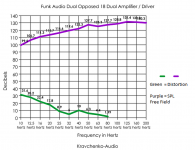
This graph is in the public domain so I can share it.
The purple line is the output from the dual 18 inch cabinet. The green line is the level of total harmonic distortion. I do have another graph that extracts the different harmonics, it just gets a wee bit busy to try and read.
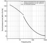
This graph gives the theshold of hearing all the way down to 1.5 hertz. And yes this means you can hear all the way down that low.
Ben I understand that you have a Klipsch low end system and a servo controlled subwoofer. So you have an idea of what you are after. I also have read quite a few times of your concert attendances. So you have first hand experience as to what music can and does sound like in the flesh.
The harmonics as used in instrument building and performance of music are there for a reason. I'm sure you agree with that. They flesh out and add gravitas to the music. Most of the power in music comes at or around 64 hertz in the bass. But the Pipe Organ is the exception to that statement.
I've been at some extraordinary pipe organs over the years. And I have studied the instrument and the music for over 30 years. My greatest bass fest was at St. Paul's in London England. Absolutely scarey. And I heard every bit of the sound be it from the 32 foot ranks or the trumpets over top the main doors.
Perception of the notes down that low are entirely dependent on the clarity of the reproduction of those notes and the sound pressure level you can achieve with your system.
@ Bach On
When you get your level matching box you will be a happy camper. Zero D gave great wiring explanations. Beat me to it!
And the studies into hearing thresholds are not built on a flimsy foundation. They are an aggregate of quite a few researchers work. The old Fletcher Mundson curves were ground breaking for the time. And important work. Drivers have changed quite a bit since those early years. And the ability to reproduce bass with less distortion is now possible.
But on your side of the argument, the reproduction must be relatively clean. And it is a tall order for most systems to achieve. But by no means impossible.
I did measurements for a driver I had a hand in designing.

This graph is in the public domain so I can share it.
The purple line is the output from the dual 18 inch cabinet. The green line is the level of total harmonic distortion. I do have another graph that extracts the different harmonics, it just gets a wee bit busy to try and read.

This graph gives the theshold of hearing all the way down to 1.5 hertz. And yes this means you can hear all the way down that low.
Ben I understand that you have a Klipsch low end system and a servo controlled subwoofer. So you have an idea of what you are after. I also have read quite a few times of your concert attendances. So you have first hand experience as to what music can and does sound like in the flesh.
The harmonics as used in instrument building and performance of music are there for a reason. I'm sure you agree with that. They flesh out and add gravitas to the music. Most of the power in music comes at or around 64 hertz in the bass. But the Pipe Organ is the exception to that statement.
I've been at some extraordinary pipe organs over the years. And I have studied the instrument and the music for over 30 years. My greatest bass fest was at St. Paul's in London England. Absolutely scarey. And I heard every bit of the sound be it from the 32 foot ranks or the trumpets over top the main doors.
Perception of the notes down that low are entirely dependent on the clarity of the reproduction of those notes and the sound pressure level you can achieve with your system.
@ Bach On
When you get your level matching box you will be a happy camper. Zero D gave great wiring explanations. Beat me to it!
The second chart shows that a 64 Hz harmonic error would have to be well below 1% not to over-power a 16 Hz note. Since that is not ordinarily achievable, when people say say "they hear" something when 16 Hz is input, they are really hearing 32, 48, and 64 Hz... and the brain does the rest or recreating the fundatmental.
Moreover, easy to "hear" something which is, say 60 dB down and honestly say they heard it and be delighted. But a different matter to say a side drum was hit in their room (ordinarily, the lowest thing on records at around 32 Hz, occasional pedals excepted).
If I am reading it right, does the first chart shows a speaker playing at a very, very loud level with distortion 120dB below from 25 Hz on up?
Ben
Last edited:
The second chart shows that a 64 Hz harmonic error would have to be well below 1% not to over-power a 16 Hz note. Since that is not ordinarily achievable, when people say say "they hear" something when 16 Hz is input, they are really hearing 32, 48, and 64 Hz... and the brain does the rest or recreating the fundatmental.
Moreover, easy to "hear" something which is, say 60 dB down and honestly say they heard it and be delighted. But a different matter to say a side drum was hit in their room (ordinarily, the lowest thing on records at around 32 Hz, occasional pedals excepted).
If I am reading it right, does the first chart shows a speaker playing at a very, very loud level with distortion 120dB below from 25 Hz on up?
Ben
Hearing at low and infrasonic frequencies Moller H, Pedersen C S - Noise Health
Here is a link to the paper. All the graphs are referenced on the left hand side and available from the link at the bottom of the paper.
The frequency threshold I posted is a distillation of this graph demonstrating the research done in this field:
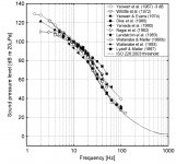
The dotted line starts at 20 hertz and is the new proposed standard for the low frequency hearing threshold. The graph has no other purpose than to report loudness on the left hand side in decibels and frequency along the bottom in hertz. No harmonics are included or referenced in this graph. It is for pure tones only.
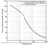
I put the proper label on the bottom of this one.
Now for the subwoofer output graph.
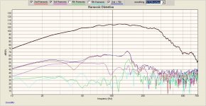
Here is the complete story. The legend telling you which color line is which harmonic is on the top.
The previous graph with the purple line was maximum output. And that with an insane amount of power. We peaked at 38 kilowatts. And the distortion components were near 27% at 16 hertz at those levels. Baccking off a bit did drastically lower the distortion though.
This graph is a more sane measurement. Notice at 16 hertz the top line is the frequency response(black line) The highest distortion component is the blue line 5th harmonic. There is an approximate 30 decibel difference between the distortion level and the desired tone at 16 hertz.
http://www.sengpielaudio.com/calculator-thd.htm
This website will allow you to calculate the difference in percentage terms. -3db is about 3% distortion.
Last edited:
The connection is not the problem. The impedance mismatch is the problem. Think 8 ohm capable amplifier being asked to drive 2 ohm loudspeakers.
There is not enough current. The rolls box solves the problem by being a dedicated pre-amplifer in series. The bass roll off is mitigated by the changing of the two capacitors as shown in the directions on Colos website.
Bach On if you need a little walk through on desoldering a capacitor from the printed circuit board please say so. But it is as easy as heating up one leg and pulling the leg up and away from the board. Only heat until you have melted the solder and get the work done quickly. Those cheap printed circuit boards do not like being heated up. The copper foil will lift on them if you abuse them with prolonged heat. Prolonged generally means more than 30 seconds.
Otherwise it is not a difficult job.
Solder wick is also your friend. http://www.amazon.com/MG-Chemicals-Series-Braid-Super/dp/B008UH393K
Helps you clean up the old solder very nicely.
https://www.youtube.com/watch?v=htrcZuK_ZsY
Mark,
So if I buy a brand new ART converter, I'll need to begin by tearing it open and changing out a capacitor to prevent roll-off in the low range.
The article said the capacitor mod wasn't required if I bought a Samson S-converter. BUT it appears that the S-Converter is no longer available except from overseas - or used.
I bought the Rolls brand which you listed as a possible candidate. Will I need to change out capacitors in that model too?
I can change out capacitors, but I'm not crazy about having to do it in a brand new product. It seems like there should be a model specific for subwoofer situations.
Bah! 😡
Bach On
- Status
- Not open for further replies.
- Home
- Loudspeakers
- Subwoofers
- 16Hz for church organ