
maybe ZM Assen euphoria 😀
...well forgive him...i fully understand...Vale was simply amazing!!!!
😀😀
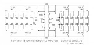
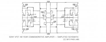
As a run up to the presentation of part 2, I have posted the original 2013
article Sony VFET 40 Year Commemorative Amplifier
You will find it under articles at FIRST WATT
This is the big brother of the DIY Sony VFET part 2
And there is great honor for he who spots the error in the simplified schematic.
article Sony VFET 40 Year Commemorative Amplifier
You will find it under articles at FIRST WATT
This is the big brother of the DIY Sony VFET part 2
And there is great honor for he who spots the error in the simplified schematic.
Attachments
JFets are in place regarding polarity , but you need gates crossed , comparing to schm as is now
So, you've been holding out on us since 2013, eh? 🙂
I jest. Thanks, Nelson.
Where are the amps now? Are they still touring?
I jest. Thanks, Nelson.
Where are the amps now? Are they still touring?
they're smashed
in OPLDF

edit :
God , give us that everyone is holding on us , as Papa is doing .......

in OPLDF
edit :
God , give us that everyone is holding on us , as Papa is doing .......
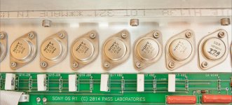
I counted 28 sit devices in the photo. I only have 4.
It's actually 24 sits with 4 irf regulators and that's mono......
48 required for stereo 🙄
and few shorts , here and there
though , I need strong coffee now , working on PCs for last 6 hours
need time for switching to Papapuzzles
here , after some coffee , still principle/basic schematic but drawn more logical
Mighty ZM , never hesitating to be dumb , in public
Attachments
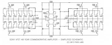
here , after some coffee , still principle/basic schematic but drawn more logical
Mighty ZM , never hesitating to be dumb , in public
edt
Thanks a lot sir Pass
Sony Big Commemorative sound very excellent and diyers can dream about.
It was first version with white bricks source resistors ?
https://www.youtube.com/watch?v=MNEt2XXOkYo
1 pair , 2 matched or 4 pairs topology are realistic for diyers
and it be lot of joy to constructs this amplifiers

Please Papa bring us little schematic for match technique target circuit.
Transistors poofff i ready know
Kind regards
ps. what happen with nice classic cool emoticone ?
Sony Big Commemorative sound very excellent and diyers can dream about.
It was first version with white bricks source resistors ?
https://www.youtube.com/watch?v=MNEt2XXOkYo
1 pair , 2 matched or 4 pairs topology are realistic for diyers
and it be lot of joy to constructs this amplifiers
Please Papa bring us little schematic for match technique target circuit.
Transistors poofff i ready know
Kind regards
ps. what happen with nice classic cool emoticone ?
Attachments

.......
My edit simply swapped the voltage values.
yup
I'm used to see you ridicule common social relations/establishments , but this time that would be too general , even for simplified schematic
(rest of Greedy Boyz are maybe forgotten that mess you made with misplaced dot in F6 , but I remember how it almost melted my brain .... )
Attachments
I guess this scaled down version must be possible to build. Though I have to order some extra VFET's 😀
The transistors, if I read right, will be like a balanced BA3 front end but with cascoding.
So probably 2sj74bl/2sk170bl JFETs with 2sj313/2sk2013 MOSFETs....
Cascoding BJT's probably 2sc4793/2sa1837.
The transistors, if I read right, will be like a balanced BA3 front end but with cascoding.
So probably 2sj74bl/2sk170bl JFETs with 2sj313/2sk2013 MOSFETs....
Cascoding BJT's probably 2sc4793/2sa1837.
Attachments
Last edited:
I have been fortunate to acquire a pair of permaneder boards from a gracious member and notice that the input voltage is 32 volts so I am to assume the voltage is regulated down to 23 volts on the board. Does anyone have a schematic for the boards? I notice that the buffer is also included on the boards.
David
David
I have been fortunate to acquire a pair of permaneder boards from a gracious member and notice that the input voltage is 32 volts so I am to assume the voltage is regulated down to 23 volts on the board. Does anyone have a schematic for the boards? I notice that the buffer is also included on the boards.
David
AFAIK, Permaneder boards had everything on the PCB, including the ref voltage regulators etc. One had to just give the 32 volts input and the the required 12V stuff. The input buffer is also part of the VFET Part 1 article. I managed to get a pair of similar boards from a member as well.
Cheers.
- Status
- Not open for further replies.
- Home
- Amplifiers
- Pass Labs
- Article - Sony VFETs part 1