Hi guys,
....just another PL (EL) 36 amplifier. Power output is 8W into 8 Ohm load.
Anode dissipation of the PL36 is ~ 20W, no problem for this tough and good sounding valve.
I "borrowed" the idea for the EL183 driver, more or less, from Yves, but I use slightly different settings.
Regards
Peter
....just another PL (EL) 36 amplifier. Power output is 8W into 8 Ohm load.
Anode dissipation of the PL36 is ~ 20W, no problem for this tough and good sounding valve.
I "borrowed" the idea for the EL183 driver, more or less, from Yves, but I use slightly different settings.
Regards
Peter
Attachments
Yes, I like PL36 valves too. Couple of schematic errors I think: the bias pot looks to be on the wrong side of the 33k resistor, and the bias smoothing cap should be from the 150k resistor (non grid end) to gnd.....
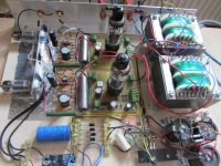
this is a working amplifier build exactly as as illustrated in the diagram...still on breadboard though.
The negative bias is generated by a voltage doubler circuit and stabilized with Z-diodes.
cheers
Peter
Maybe, but the trimmer potentiometer does not regulate anything (especially not the value of the negative bias G1!), except that changes the value of the drain resistor! The current through the trimmer potentiometer is zero, so is no actual voltage drop!
Maybe, but the trimmer potentiometer does not regulate anything (especially not the value of the negative bias G1!),/QUOTE]
...of course it does and it works perfectly 🙂
The pcb that carries the PL36 valves includes the circuit fot the negative bias raw supply. Only the lower pcb is populated. This bias voltage is fed through to the upper pcb. The bias can be adjusted for each PL36 separately with a individual pot.
The pcbs is from a commercial kit, that was offered by Experience Electronics. It was published in ELRAD (a German electronics magazine) in 1990. Originally this pcb was intended to be used with KT88 or EL34. I modified it a little bit.
Try it out! 🙂
EL36triode + Ra=3k + Vb=360V and 8W ? Wonder if you even get 4W.
Mona
Dear Mona,
unbelievable but true:
undistorted 1kHz sine wave across 8 Ohm resistor is 8V, clipping occurs at 8,25V!
I use a high quality output transformer and did a lot of testing (different driver tubes etc.) over the last months.
The amplifier is in daily use and by the way dead quiet, no hiss, no hum...nothing but music!
cheers
Peter
.......
...of course it does and it works perfectly 🙂..........
it probably does but you certainly didn't drew that schematic properly , at least bias part
edit:
8Vpp across 8R is exactly 1W , not 10W
when speaking of sine wave , you always quote Vpp , so ...... ?
Last edited:

A couple things:
1- As previously noted, the bias adjustment can not work as there's no current flowing through the bias adjustment potentiometer. So unless the schematic is wrong, there's no bias voltage adjustment, unless of course the grid is drawing current, which is unlikely.
2- I don't see the output section delivering 8-watts (RMS) with the available plate voltage and the 3000 ohm load. Note that Zen specifically stated 8Vpp (peak-to-peak), not RMS. The link you provided assumes the voltage is RMS. So, if you are getting 8V RMS into an 8-ohm load than you are getting 8-watts output. To calculate RMS volts, you divided Vpp by 2.818, resulting in 2.83V RMS, which would be 1-watt output.
Regards, KM
Dear all,
no further comments from my side to comments like:
....this does not work... or ....this cannot be true...this is wrong
I suggest that you try things out, instead of speculating.
regards
Peter
no further comments from my side to comments like:
....this does not work... or ....this cannot be true...this is wrong
I suggest that you try things out, instead of speculating.
regards
Peter
You have surely a very nice amp that function very well...
But not build the way you present it here .
Mona
But not build the way you present it here .
Mona
Dear Peter,
I suggest you learn how to make actual measurements and calculations instead of making declarations that ignore basic electrical laws. You may also want to physically look at the circuit board and create a schematic from it. Bottom line, if the bias adjustment potentiometer works, then the schematic is NOT what you posted.
Regards, KM
You have surely a very nice amp that function very well...
But not build the way you present it here .
Mona
Dear Mona and Davorin,
I must apologize.....found the mistake in my drawing and present the corrected schematic.
cheers
Peter
Attachments
Last edited:
Member
Joined 2009
Paid Member
I heard a Russian equivalent, 6S31P I think? also SE and it sounded glorious. One of these ays I should build one too.
- Home
- Amplifiers
- Tubes / Valves
- PL36 (triode) SE