@nigel: This is not the lounge. Can you try and contribute rather than meander off on one please.
Don't know how much care has been taken regarding torque and speed accuracy but saw an Audio Technica LP120 at friend's place. It was brand new purchase and when l looked at the strobes when platter is running they seemed absolutely not moving. But I have doubts that almost stand stillness of strobes is not a measure of speed accuracy at higher level. Wonder if any one has measured modern turntables. Also a brand new Audio Technica LP120 almost touches the price level of second hand SL-1200.
Regards.
Regards.
The Feikert test suite is used a lot these days Dr.Feickert:😛latter Speed even the subjective Fremer uses it, sadly though he doesn't share the spectral plots that give the most interesting information. I must buy one as well as an accelerometer amp PCB.
Ahh OK. I misinterpreted various posts in the linked thread, where eccentricity of vinyl and different test vinyl with different test tones were impediment in analysing measurements obtained.As the test disk is not measuring speed accuracy in the traditional sense, and it gives you data you cannot get with an optical reader I don't think so. cheap PCs and new test disks is a real boon to getting under the surface of what is happening.
Regards.
If you have the right software you can filter out the eccentricity as that will be a fixed low frequency FM. Interpreting what it all means in audible terms is still as far as I can tell under discussion at least amongst the DIY crowd. But being able to gather data is a good start!
I saw a link to this thread posted on diyaudio a couple years ago, it's an interesting approach to measuring platter speed:
Turntable speed analysis - Page 4 - pink fish media
Turntable speed analysis - Page 4 - pink fish media
Audio Technica LP120, I and Noel Keywood of HiFi World independently measured two separate sample, don't go there !
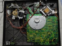
Been doing a bit more research online, as still not got around to further disassembly of my Q33. Turns out that they have tried quite a few configurations of the same basic motor/bearing/PCB configuration. It also looks like Calvin picked the right one (see page 5) and my £10 offering is going to cause some interesting packaging. However that is not stopping me!
Whereas the Sl-1200 has the motor effectively sitting on the bearing, the Q33 is built 'hanging' off the plinth, with the metal plate handling the torque. That plate will effectively become the level of the bottom plinth, which will mean I will need to put standoffs to support the PCB and think about ventilation. Certainly not worth sticking with the existing plinth design.
Given the size of void I will need for the PCB I am considering having two plinth layers with antivibration mounts between.
It does look as if you could completely decouple motor and bearing as long as you can keep the alignment. Not sure if there could be any benefit from that, but an interesting potential implementation.
Attachments
Thanks Benb and Dave.
Billshurv, Shouldn't only transformer be ventilated ? Spacer between PCB and plinth would be OK ?
Billshurv, Shouldn't only transformer be ventilated ? Spacer between PCB and plinth would be OK ?
..also with proper cut you can couple the small metal disc holding the thrust plate to the plinth so bearing noise gets drained.

Thanks Benb and Dave.
Billshurv, Shouldn't only transformer be ventilated ? Spacer between PCB and plinth would be OK ?
Should be. Only 10w to lose, but silicon you cannot replace easily! Air gap should be fine with a way for air to circulate.
Aside: was starting to take a look at my Kenwood KD-550, which is servo based DD. I now see why the cheap TTs didn't use quartz. The FD servo function is all handled by one small chip giving a relatively teeny PCB. Quartzing that will take some time!
The quartz is a non issue. If you match COG caps and 15 or 50 ppm resistors depending on needs the stability is equal to quartz type or better. More likely a phase locked loop or similar is used and that is the bigger deal. The SVF oscillator of the Garrard 501 is stable to 6 minutes a day used as a clock and is COG+R. The time keeping mostly down to the adjustment steps of the pot and could be better if wanted .
As best I know it, the natural speed of a DD is vastly more than it needs. I have never studdied the exact numbers so must make a guess or two. 24 pole steppers seem to resonate at about 70 Hz. This makes them ideal 50/60 Hz motors, they don't like 25 Hz I suspect because the magnetic circuit is like transformers starting to need a larger magnetic field. A motor is a rotating transformer more or less and shows this in the spectrum of vibration. This says steppers were derived from synchronous types wound for a lower voltage. At a wild guess DD motors look to favour closer to 100 Hz and rotate at circa 300 RPM when at or near resonance. Whatever the truth 33 1/3 is not the ideal speed. Thus the power is fed in pulses. How well the design creates the pulses dicates how the nasty switching transients cause problems. As mass has inertia this will damp the transient. It is tempting to think that a high mass platter the turntable, that can not start from rest would be best. The device known to us as a finger would be the answer to start it.
Now for the hype. Denon said they used sine waves as this will suit better and protected it with a patent. If in free rotation this idea is nonesense as the current drawn regardless of waveform type is a distorted sinewave most like a triangle wave. However I made a mistake. On switching the sine wave is better. This must matter. The question is does the integration of square to sine happen within an ideal time period. That I can not say. The mass seems to be the key question to the integration. Ideally integration which is faster than the feedback process. A mechanical time constant of some duration related only to mass.
Here is an idea. As buffer amps are simple to design buffer the square wave output and filter it . If so give the original amplifer a load to drive similar to the real one. The gain of the buffer might need to be 1.2 or whatever to compensate for the true rms values. With luck the servo will know no difference, yet the initial switching will be nicer. Any fool can see this is the nub of the problem. I have heard a SP 10 cut records. Fine on low modulation. Not great when Peter Gabriel So. The Scully mass was fine so not that and the SP 10 would drive it. What it can only be is the cutting loading working against the SP10 servo's. I supect if the Scully mass was increased and then needed a hand start it would be better. I suspect conversion to sine wave also a good idea.
The little JVC my friend has seems better on this . Wonder if JVC just paid Denon a liecence fee ?
The Garrard 201 circa 1937 was a DD exactly as they are today except meachanical regulation.
I gained a lot of experiance on this with the Loricraft record cleaning machine. I had a 12 V motor for an oven. I used a NE555 to make various mark space ratios for getting the very slow speed I wanted. I thought torque would be unchanged. Not so. It proved to be very hit and miss. I then moved to synchroous and gearbox which is fine. Wanting half speed I used a CD4020 and the mains itself as timing pulse. All CD4020 Q ports were tried as the mark space ratio is always 50% regardless. The only one that worked well was the one not intended which is the Q0 output. This was fed to a MOC3020 which usually is a control opto coupler. It was OK for the small current used at 230VAC. This made me think that all motors must really be like this. There comes a point where if the motor is off more than on it is not ideal. The idea of this mod was to give records longer to clean. The modern liquids could use that to advantage. Alcohol not. In the end I settled on 1 minute and asked the people who use alcohol to keep the record wet just ahead of the suction arm using the cleaning brush.
You get a sine wave for free out the motor, so silly not to use it. well not quite free as you have to do envelope detection, but certainly at a bargain price. Back in the 70s that mattered. In 2015 silicon is cheap.
Very OT and will be another thread when my round tuit order from amazon arrives, but a scan through the specs for this DRV8308 | Brushless DC Gate Drivers | Brushless DC (BLDC) Drivers | Description & parametrics looks like we could have something very useful On a scan seems to tick all the boxes for a modern DD motor controller. I need to read more thoroughly though.
Mmmmmmmmm the SP-10 is driven by a 3 phase sinewave, not pulses, wherever did that come from ! 😕
the many motor types can get confusing in fairness, but if you look at DD as a 3 phase motor (for that is what it is the good stuff) then it all makes sense 🙂
You get a sine wave for free out the motor, so silly not to use it. well not quite free as you have to do envelope detection, but certainly at a bargain price. Back in the 70s that mattered. In 2015 silicon is cheap.
Be sure by inserting a small resistor in circuit to see the waveform, 1 R perhaps or even less if the scope is sensetive. If R is higher you risk a false result ( RL time constant) This will let you see what is happening. If it looks like a sine wave then mass is the next question. After that the harder things come into play. Just amplifiying the original and with first order filtering could work. To be able to set your own level could be interesting. Maybe a fan to cool the coils if asking for more toque. Going back a step. If there is a surplus of voltage and current from the new amp a series resistor could do some good if lucky. Again use the scope to see. It might just stop the amplifier clamping hard to the motor ( low damping factor ) .
- Status
- Not open for further replies.
- Home
- Source & Line
- Analogue Source
- Technics SP-10/SL-1200 alternatives