Today was assigned to another exercise in futility. Organizing the lab. By good fortune I found a box of stuff that I haven't looked into for a number of years. I quickly forgot about the mission at hand and was transported back to those halcyon days of yesteryear. A couple of beers helped in the transportation effort. Anyhow, contained within the box were the mortal remains of an audio project from my early days of tube building. This particular boondoggle was aimed at the construction of an electrostatic loudspeaker. Well, more than a speaker (anyone can build an ESL), but rather an ESL system.
My plan was to drive each speaker with a DIY triode that could hold off 10 KV and drive the panels directly off the plates. This output tube would then be controlled by a DIY planar electrode triode with lower voltage specs. The goal was to make a small bookshelf size pair of panels that would easily fit on a desktop or workbench and spray the area with the glorious sounds that can only come from planar drivers.
To enhance this madcap scheme, I decided to make the diaphragms from stretched Mylar films that were then coated with a few micro-inches of evaporated copper. This coating was applied in a vapor deposition bell jar system. A coating applied by this technique is extremely controllable as to thickness and placement.
I decided to test the tubes to see if they were still under vacuum and was pleased to find that the filaments still work and the the vacuum left inside could still hold off high voltage. I was surprised that there was any life left in them because the tubes were sealed with epoxy when they were constructed. The panels are still useable for testing and I think I'll resurrect the project now that I'm into building vacuum tubes again. If anyone is interested in this reprise I'll report on any progress.
For many years I said nothing can compare to direct high voltage drive for ESLs using a Sanders-like amp.
(I've recently taken my 1975 ESLs out of the storage and am driving them with transformers and mic-based DSP EQ. Not sure what I have now is inferior to direct drive, but hard to compare listening today to memory maybe 10 yrs back when I last used my direct drive amp.)
Ben
(I've recently taken my 1975 ESLs out of the storage and am driving them with transformers and mic-based DSP EQ. Not sure what I have now is inferior to direct drive, but hard to compare listening today to memory maybe 10 yrs back when I last used my direct drive amp.)
Ben
Was there a particular reason you chose copper for coating the diaphragm? Generally it is desirable to have a highly resistive coating so the ESL panel operates in the low distortion constant charge mode. Copper is one of the most conductive element there is. I guess I would also be concerned about the copper oxidizing....I decided to make the diaphragms from stretched Mylar films that were then coated with a few micro-inches of evaporated copper...
Am I understanding you correctly that you are building your own custom vacuum tubes designed specifically for direct drive of ESLs?The panels are still useable for testing and I think I'll resurrect the project now that I'm into building vacuum tubes again. If anyone is interested in this reprise I'll report on any progress.
If so, I would be interested to see your progress reports in this thread.
Bentoronto - I'll have to agree with your assessment of the sound quality of directly driven ESL's. The small panels that were constructed sometime back were truly astonishing. I know that I'm on thin ice making my own claims, of course!
Bolserst - I chose to use copper because the vacuum vapor deposition system was already set up to deposit Cu onto some planar magnetic Mylar panels that I had been experimenting with. There are a lot of myths and legends that accompany the rules of constructing ESL panels. I chose my design parameters based on the B&k microphones that I use for lab measurements. These microphones use a solid metal foil as the diaphragm. To calibrate these microphone cartridges and preamps I use a B&K electrostatic actuator. This is about as good as it gets for linearity and low distortion. The actuator's frequency response deviation is +/- 0.6 dB from 2 Hz To 200 kHz. I just decided to experiment with a much larger version of it. I must say that I find many of the assumptions about how electrostatic and planar magnetic speakers work to be rather amusing in some of the descriptions I've seen. To each his own!
As far as the Cu oxidizing, It could be an issue over a long period of time. That's a whole other topic. My plan was to eventually replace the Cu with gold. At the time Au looked very cheap compare to the prices today. Even so, with today's prices the amount needed for depositing a few micro-inches of it are still compelling.
I've made many vacuum tubes over the years and still find if very rewarding. Here's a link to some of them and their characteristic curves. These are just toys from the past. The lasted variety will be much improved.
http://www.diyaudio.com/forums/tubes-valves/274226-testing-diy-triodes.html
Last edited:
ESL microphones like the B&K units operate in a different manner than typical ESL loudspeakers, so using them as a guide may not be the best idea. For the B&K ESL pressure microphones(sealed back chamber), the upper bandwidth limit is set by the diaphragm resonance frequency. Hence the use of metal foil that can hold the required high tension for a 40kHz resonance and be stable for years. Below resonance, the output of the microphone is directly proportional to applied pressure. This is because the displacement amplitude of a stretched membrane for constant applied force is independent of frequency below resonance. So, the motion of the microphone diaphragm is exceedingly small over the whole operating range. This is why the distortion of the B&K microphones is low even with a fully conductive diaphragm operating in constant voltage mode.…I chose my design parameters based on the B&k microphones that I use for lab measurements. These microphones use a solid metal foil as the diaphragm.
ESLs used as dipole loudspeakers operate differently from ESL pressure microphones. For example the diaphragm resonance sets the lower frequency limit(not HF limit as with microphone). Also, for flat far field pressure response the diaphragm displacement amplitude must increase as you go down in frequency. Once diaphragm excursions start to exceed about 15% of the air-gap width, the inverse square law distortion starts to show up. If you keep the diaphragm excursion down by limiting the lower bandwidth of your design, constant voltage mode works just fine without producing too much distortion or diaphragm instability.
I hear ya, but hopefully constant charge operation of ESLs didn’t fall into that category for you.I must say that I find many of the assumptions about how electrostatic and planar magnetic speakers work to be rather amusing in some of the descriptions I've seen. To each his own!
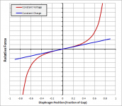
The theory is well documented in texts/papers by Hunt, Walker, Baxandall, etc... and experiment confirms the fundamental inverse square law of electrostatic forces when operating in constant voltage mode. Attached image shows a comparison of the diaphragm force vs diaphragm position for the two modes of operation. As mentioned above, keep excursion down and constant voltage mode works just fine.
Very cool, Thanks!I've made many vacuum tubes over the years and still find if very rewarding. Here's a link…
Several of those you built look like ones from the 1920s radios I collect.
I recall building a triode in AP physics class in high school...used a test tube for the glass envelope.
What fun 🙂
Attachments
Last edited:
Bolserst - Thank you for the discourse. As mentioned, the ESL's were meant to be something that could produce a pleasing level of reproduction in a small space like a desk, office cubicle, or workbench. The diaphragms measure 7" X 9". I had no interest in typical listening room sound pressure levels. I have planar magnetic drivers for that job.
Following the model of the B&K actuator, but reversing the order, the bias supply was connected to the diaphragm and a single stator was used as the ground plane. I could then run the bias up until the diaphragm was at a desirable displacement position and then modulate the HV. This allows the diaphragm to use its own spring tension to act as the restoring force without the need of a second stator. Sort of like a single ended class A amp. Yes, the displacement was small, but the SPL was equivalent to a good table top radio that isn't being over driven.
As a side note I'd like to point out that typical B&K laboratory microphones are all vented behind the diaphragm. If they weren't they would be barometers and never stay in calibration. In fact, many of the vacuum gauges that I use are capacitance manometers. They are extraordinarily linear and indifferent to the gas or non-condensable vapor species they are measuring.
I would also like to thank you for confirming that a working triode can be easily fabricated even by kids in high school!
Hi,
SE-ESLs have been used in thousands on old radios as tweeters.
Due to the non-linear drive excursions must be kept small for the THD to remain reasonably small.
This restricts the useable bandwidth of a SE-ESL to the upper-mids/highs.
As one probabely needs a means of protection for the delicate membrane anyway, a second stator comes handy, improving the behaviour of the panel at the same.
jauu
Calvin
Just curious, did you use a rear chamber like the B&K? or were you operating your ESL as a dipole.Following the model of the B&K actuator, but reversing the order, the bias supply was connected to the diaphragm and a single stator was used as the ground plane. I could then run the bias up until the diaphragm was at a desirable displacement position and then modulate the HV. This allows the diaphragm to use its own spring tension to act as the restoring force without the need of a second stator.
Note that for single ended ESLs, the bias induced spring tension(often called negative compliance in texts) is also non-linear. In fact if I recall the Hunt text correctly the displacement position involves a cubic function of the bias voltage. You will notice this as a rapidly increasing diaphragm deflection beyond a certain point as bias voltage is linearly increased. But, as Calvin mentioned and you experienced, performance can still be quite good as long as you keep diaphragm motion small. If/when you are in interested in experimenting with higher SPL, I would recommended taking Calvin's advice. Add a second stator and a high value resistance between bias supply and diaphragm. The negative compliance term becomes linear, and distortion performance is improved when diaphragm motion is not negligible.
Yeah…I originally had a comment in my post about the mic back chamber having a tiny vent tube but then removed it to avoid overcomplicating things with unnecessary details. But now that you have brought it up…hahaAs a side note I'd like to point out that typical B&K laboratory microphones are all vented behind the diaphragm. If they weren't they would be barometers and never stay in calibration.

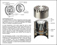
In case others are curious about the vent tube, attached is a description and pics pulled from B&K literature.
Attachments
Yes, I did use a backplate, but since the diaphragm was already electrostaticly offset I didn't consider it to be stator as such. It was operated as a dipole radiator.
I'd like to do a 'reset' here and bring us back to what the project was all about. I wanted to see how well the new tube design worked and needed to have an ESL to test it with. The speaker project was a default design for that purpose. I simply used what was around the lab and saw the microphone paradigm as a place to start. The real project was to design a DIY HV triode that could replace the transformers typically used with ESLs.
I was hoping that someone here might be interested in that aspect of the experiment. I didn't anticipate that the thread would be shunted into a protracted discussion about the theories and opinions of panel designs.
OK. Are you going to connect the diaphragm, stator, or stators to the tube or tubes directly or through a capacitor or capacitors or a mild step-up transformer (or transformers?)? (Is that 6 questions?)
Ben
Got to add, I am really intrigued over the possibility of DIY vacuum tubes. Who would have thought it possible?
Is the goal of solid-state high-voltage amps still elusive?
Ben
Got to add, I am really intrigued over the possibility of DIY vacuum tubes. Who would have thought it possible?
Is the goal of solid-state high-voltage amps still elusive?
Last edited:
Yes, I did use a backplate, but since the diaphragm was already electrostaticly offset I didn't consider it to be stator as such. It was operated as a dipole radiator.
I'd like to do a 'reset' here and bring us back to what the project was all about. I wanted to see how well the new tube design worked and needed to have an ESL to test it with. The speaker project was a default design for that purpose. I simply used what was around the lab and saw the microphone paradigm as a place to start. The real project was to design a DIY HV triode that could replace the transformers typically used with ESLs.
I was hoping that someone here might be interested in that aspect of the experiment. I didn't anticipate that the thread would be shunted into a protracted discussion about the theories and opinions of panel designs.
Plenty of people are interested in direct drive esl , with HV tubes, but the ideas never seem to actually come together into a working project. The Modjeski amp is the only currently avaliable direct drive tube amp available, and maybe another one in Europe, that's it. Theres a couple of published circuits , but very few reports of successful integration with panels.
Go for it, we will be very interested if you can make it work.
BTW I've heared the Modjeski amp with Acoustat panels, and I dont think, for all the complexity that its much better than my Acoustat with very high power, good quality amps into the step up transformers.
1988-89 I had the Acoustat Xs with the servos tube amps...I had never heard the Acoustat 121 interfaces....I owned an like tube amp Sound....But I new there was a down side with the Acoustats OTL tube servos driving panels...it was the sound of compression ...
The Sound would get darker....it was also the fact the the Xs had the panels in a box....an the panels set down on the floor....but I pulled the panles tube amps out of the boxes ....got the panels up off the floor 10"....still sound got darker the harder you drove the tubes...
Years later I ran my Acoustat panels an ML off the plates of a jadis defy 7 tube amp....6550s......sound was vary close to the Acoustat tube Servos...
Also I got into the Atma-Sphere OTls an ran them thought the Acoustat 121 interfaces...an the Sound was Vary close to the drict-drive sound....
In the end I got the best sound was with SS amps driving tranfourmer coupled fullranged ESLs...so I say good luck have fun but some how this seams to never works out..
All just ones mans finding...pic of theXs
Attachments
![$_57[1].jpg](/community/data/attachments/438/438916-76345938c25b5088cf3752cc941fb999.jpg?hash=djRZOMJbUI)
Plenty of people are interested in direct drive esl , with HV tubes, but the ideas never seem to actually come together into a working project.
Hard for me to believe I made one that worked so well around 1975, similar to Sanders's design. I'm not that skilled or experienced or had the tools for R&D. But did it. Ran flawlessly for decades.
Unlike motional feedback experiments, ESLs are quite forgiving and hard to destroy electrically... although not true of the humans surrounding the gear.
I think the key is to not design am amp to drive a capacitor. Design it to drive a load of resistors... with a small cap (the cells) across the resistors.
Ben
1988-89 I had the Acoustat Xs with the servos tube amps...I had never heard the Acoustat 121 interfaces....I owned an like tube amp Sound....But I new there was a down side with the Acoustats OTL tube servos driving panels...it was the sound of compression ...
The Sound would get darker....it was also the fact the the Xs had the panels in a box....an the panels set down on the floor....but I pulled the panles tube amps out of the boxes ....got the panels up off the floor 10"....still sound got darker the harder you drove the tubes...
Years later I ran my Acoustat panels an ML off the plates of a jadis defy 7 tube amp....6550s......sound was vary close to the Acoustat tube Servos...
Also I got into the Atma-Sphere OTls an ran them thought the Acoustat 121 interfaces...an the Sound was Vary close to the drict-drive sound....
In the end I got the best sound was with SS amps driving tranfourmer coupled fullranged ESLs...so I say good luck have fun but some how this seams to never works out..
All just ones mans finding...pic of theXs
Yeah, Have two pairs of Carver Sunfires driving each transformer in my 2+2's, slightly modified HT supply, slightly modified crossover, its sublime sound, as good as I've heard in 40 years of audio.
Hard for me to believe I made one that worked so well around 1975, similar to Sanders's design. I'm not that skilled or experienced or had the tools for R&D. But did it. Ran flawlessly for decades.
Unlike motional feedback experiments, ESLs are quite forgiving and hard to destroy electrically... although not true of the humans surrounding the gear.
I think the key is to not design am amp to drive a capacitor. Design it to drive a load of resistors... with a small cap (the cells) across the resistors.
Ben
Well I'd like to see it, but its always talk and nothing comes from it, hopefully you'll prove me wrong.
Hi,
But it all depends on the circumstances.
Hybrid-Panels would be easier to drive due to reduced bandwidth than fullrangers.
But then there needs to be made the additional differentiation between non-segmented and segmented panels.
Due to their lower effective HF-capacitance segmented panels require alot less drive current at high frequencies, resp. feature a higher bandwidth limit at the amp´s current limit.
Typically they require more drive voltage, especially fullrangers.
Simple calculations/sims show that a amp designed for full power bandwidth >>10kHz quickly becomes impractical heat and wattage wise, even for segmented panels (>>100W).
Also segmented fullrange panels require voltage levels way above simple solidstate circuits.
One could dicuss about how much fullpower bandwidth is needed, but nobody wants to listen to a current clipping amp, not to think about what happens during the amp´s overload recovery time (if it ´recovers´ anyhow).
So there is no one-fits-all amplifier, but rather two classes of amps are required, depending on the Panel design, required bandwidth and characterized by higher voltage/lower current and lower voltage/higher current.
If executed well, a ESL Panel forms a high quality Cap.
The low leakage represented by a very high R-value in parallel to the Panel´s Cap-value.
The series resistance (similar to ESR) is negligable low though.
This equals a close to -90° phase shift, suggesting an amp designed to drive Caps not resistors (rather current drive than voltage drive).
Things may change towards a ´resistor design´ when talking about electrically, resistively segmented Panels.
The series resistors would reduce the complex phase shift towards real, the more so the higher the R/C ratio, hence towards higher frequencies.
Still though the amp needs to be designed to perform stable into quite complex loads.
jauu
Calvin
That may apply for a single special case only. 😉I'll have to agree with your assessment of the sound quality of directly driven ESL's.
But it all depends on the circumstances.
Hybrid-Panels would be easier to drive due to reduced bandwidth than fullrangers.
But then there needs to be made the additional differentiation between non-segmented and segmented panels.
Due to their lower effective HF-capacitance segmented panels require alot less drive current at high frequencies, resp. feature a higher bandwidth limit at the amp´s current limit.
Typically they require more drive voltage, especially fullrangers.
Simple calculations/sims show that a amp designed for full power bandwidth >>10kHz quickly becomes impractical heat and wattage wise, even for segmented panels (>>100W).
Also segmented fullrange panels require voltage levels way above simple solidstate circuits.
One could dicuss about how much fullpower bandwidth is needed, but nobody wants to listen to a current clipping amp, not to think about what happens during the amp´s overload recovery time (if it ´recovers´ anyhow).
So there is no one-fits-all amplifier, but rather two classes of amps are required, depending on the Panel design, required bandwidth and characterized by higher voltage/lower current and lower voltage/higher current.
Could You explain a bit??I think the key is to not design am amp to drive a capacitor. Design it to drive a load of resistors... with a small cap (the cells) across the resistors.
If executed well, a ESL Panel forms a high quality Cap.
The low leakage represented by a very high R-value in parallel to the Panel´s Cap-value.
The series resistance (similar to ESR) is negligable low though.
This equals a close to -90° phase shift, suggesting an amp designed to drive Caps not resistors (rather current drive than voltage drive).
Things may change towards a ´resistor design´ when talking about electrically, resistively segmented Panels.
The series resistors would reduce the complex phase shift towards real, the more so the higher the R/C ratio, hence towards higher frequencies.
Still though the amp needs to be designed to perform stable into quite complex loads.
jauu
Calvin
Well I'd like to see it, but its always talk and nothing comes from it, hopefully you'll prove me wrong.
Are you saying that I am lying when I wrote, "I made one... around 1975" and used it for decades?
You should be more careful in your choice of words and thoughts.
Ben
Last edited:
Not sure I know enough to explain much. Each channel of my amp had a load of maybe 15kOhms (I could be off by a factor of 5... long time ago). A whole bunch of power resistors on a large board. I can't remember i the series of resistors was grounded in the middle or not. The ESL stators were attached directly to the tube anode caps on top of the 8034 tubes (hope I have that right). I think that's like a Sanders amp.Could You explain a bit??
The Dayton-Wright cells, run in parallel with that resistor load, are quite wide spaced with very low capacitance. So the amp was seeing mostly the resistors.
BTW, in addition to the 2400 volt B+, I had the usual high voltage DW bias, totally maybe 10kv or more together. Crossed over at 140 Hz, not enough ooomph for Mahler's Second Sym finale, but pretty loud.
In a city like Toronto, in the days long before the web, you could find inexpensive oil-filled high voltage power supply capacitors and all the electronic goodies you need. I believe much of what I built long ago had once flown over Europe in war planes.
Ben
Last edited:
Are you saying that I am lying when I wrote, "I made one... around 1975" and used it for decades?
You should be more careful in your choice of words and thoughts.
Ben
Calm down sunshine, your being very defensive, I dont doubt your word, but I'd like to see something apart from words.
- Status
- Not open for further replies.
- Home
- Loudspeakers
- Planars & Exotics
- Tubes and ESL's