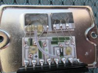
I'm fixing this amp for a mate and have no experience with these power module type outputs? The amp was dead except for the power light when I got it from him,he said he got it from an old bloke who had it from new. The main filter caps 8,000uf were bulging and read 620uf and 510uf,so I fully recapped the whole amplifier.The right channel power module SP-40W had failed,I took it out to measure it and found pin 3 had no reading.What I need to know,in case I blow up the new SP-40W module is if Q9 the transistor that has its connector going to pin 6 is going to read -1.2v (as in the schematic) when I install the new SP-40W power module? At present Q9 collector reads -35.6v? Ive checked all the discrete transistors and they read OK.There was one completely failed cap: 100uf,25v and another 100uf,25v badly bulged reading 200nf, both of them on the power supply to the failed SP-40W. I opened up the failed module to have a look. I could make out burn marks on the tiny wires going into the semiconductor at the top of the photo.These modules are as rare as hens teeth and I need to know its OK to install the new one without blowing it up!
Attachments
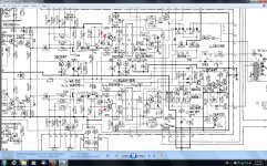
Without the module in place you will see near rail voltage at pins 2 and 6. If you would like to test that the front section is working as far as DC levels are concerned, jumper pins 2,4,and 6 of the modules socket and measure the voltage there. It will be somewhere between +/- 1.2V.
When you install a new module (if you can find one, which shouldn't be possible), power the amp up with a dim bulb tester (google it) to remove the risk of things blowing up.
they contain 2 predriver transistors 2 power transistors, 2 .33 ohm resistors to output
and the bias network. the bias is 3 diodes plus a resistor.
the driver is shot. 1.2v is the correct voltage at the input pins.
STK 0050 is similar
and the bias network. the bias is 3 diodes plus a resistor.
the driver is shot. 1.2v is the correct voltage at the input pins.
STK 0050 is similar
Last edited:
Without the module in place you will see near rail voltage at pins 2 and 6. If you would like to test that the front section is working as far as DC levels are concerned, jumper pins 2,4,and 6 of the modules socket and measure the voltage there. It will be somewhere between +/- 1.2V.
Sorry about the late reply.The email went into my junk folder for some reason? What do you mean by testing the front end? I cant work out what you mean,do I use some jumper leads to connect where pins 2,4 and 6 go to, then measure the voltages from 2 and 4 then 4 and 6?
they contain 2 predriver transistors 2 power transistors, 2 .33 ohm resistors to output
and the bias network. the bias is 3 diodes plus a resistor.
the driver is shot. 1.2v is the correct voltage at the input pins.
STK 0050 is similar
Are you saying that's what the SP-40W power module contains,all of those components?

When you install a new module (if you can find one, which shouldn't be possible), power the amp up with a dim bulb tester (google it) to remove the risk of things blowing up.
I found a used one on fleabay the first time I looked for $12.50 (it had been tested) with free postage.I must've been lucky. Don't worry Ive had a DBT for years and its saved me a lot of times.
Without the module in place you will see near rail voltage at pins 2 and 6. If you would like to test that the front section is working as far as DC levels are concerned, jumper pins 2,4,and 6 of the modules socket and measure the voltage there. It will be somewhere between +/- 1.2V.
What do you mean by jumper pins? Does that mean I use jumper leads on those pins somehow? Honestly I cant for the life of me work out what you mean?
all that is in there. note the 5 connections on the one power output module (transistor) and 3 on other. the lower module has 2 drivers and bias network. sets 1.2v on each input pin to compensate for 4 x .6v Vbe voltage.
the .33 emitter resistors to protect outputs from thermal runaway
the .33 emitter resistors to protect outputs from thermal runaway
Last edited:
all that is in there. note the 5 connections on the one power output module (transistor) and 3 on other. the lower module has 2 drivers and bias network. sets 1.2v on each input pin to compensate for 4 x .6v Vbe voltage.
the .33 emitter resistors to protect outputs from thermal runaway
No wonder I'm getting confused. The datasheet for SA-7300 that I have on SP40W says it has 4 diodes in series 5 resistors and 2 Darlington transistors,one is NPN the other PNP? The main thing is that its going to drop the Q9 collector and pin 6 voltage down from -35.6v to -1.2v when I install the module! Is that right?
Attachments
- Status
- Not open for further replies.
- Home
- Amplifiers
- Solid State
- Pioneer SA-7300 advice needed.