I have today removed the rc filter 1200 pf ceramic NP0 type with a view to moving it upstream to my buffer. Based on what I am hearing I suspect these smt capacitors are not as transparent as they should be.
Dear DAM 1021 modifiers I think it would be nice to have a place where we could add all HW modifications to the DAM 1021, so that we do not have to check through all these posts. I was considering doing this myself but I am not sure that I have enough knowledge to manage such a thread. Anybody else willing to take the responsibility?
I have today removed the rc filter 1200 pf ceramic NP0 type with a view to moving it upstream to my buffer. Based on what I am hearing I suspect these smt capacitors are not as transparent as they should be.
interesting, could you say more about what you are hearing?
My experience, as I've expressed in the DAM output stage thread, is that these small caps, even with cut-offs well above the audio range, can have a significant effect on sound.
I have today removed the rc filter 1200 pf ceramic NP0 type with a view to moving it upstream to my buffer. Based on what I am hearing I suspect these smt capacitors are not as transparent as they should be.
On my list of things to do.
I am not using a line stage of any kind due to the robust output of the SOEKRIS even from the "raw" output so will likely replace it with another dielectric.
One of those basic mods. What cap I replace it with will probably cost more than ten times as much as the production cap.
SOEKRIS made canny choices for the components to keep the price so affordable (low!) and the thing box stock (w/spzzzzkt's filters) sounds very fine to me. But from experience there is no doubt it can be better still with a deluxe power supply and component swaps such as this.
Hope to get my PS in place this weekend.
I finally received my isolated USB to RS232 today and it works flawlessly with the dam, no more ground loop noise with serial plugged in.
Isolated USB TO RS232 Converter USB TO Serial 2 5KV Isolation | eBay
I know Soekris is supposed to enable the isolated TTL interface eventually but I couldn't wait any longer, and besides the TTL interface will be better used integrate into an arduino for LCD/front panel button control.
EDIT: The isolation IC used is an Analog Devices ADM3251. http://www.mouser.com/Search/Refine.aspx?Keyword=adm3251
Because it has an internal isolated charge pump dc-dc converter to generate the +/-10V for RS232 it still uses just the 3 wires to the dam.
Last edited:
interesting, could you say more about what you are hearing?
My experience, as I've expressed in the DAM output stage thread, is that these small caps, even with cut-offs well above the audio range, can have a significant effect on sound.
To my ears in my system the onboard SMT NPO 1200pF contributes a degree of harshness to the presentation. FYI I am using the raw output into a DCB1. If you are brave maybe try it for yourself.
Last edited:
I suspect you're not hearing a problem with the capacitor - I've noticed that removing (or reducing) caps around the feedback loop of an opamp driven from a DAC (so subject to fast edges) also improves the SQ, reducing harshness. Its more than likely due to the cap's loading on the output stage of the opamp and hence the opamp's power supplies, not that the cap itself isn't transparent enough - NP0 caps are about as close to perfect caps as its possible to buy.
I have today removed the rc filter 1200 pf ceramic NP0 type with a view to moving it upstream to my buffer. Based on what I am hearing I suspect these smt capacitors are not as transparent as they should be.
so what did u replace it with?
I suspect you're not hearing a problem with the capacitor - I've noticed that removing (or reducing) caps around the feedback loop of an opamp driven from a DAC (so subject to fast edges) also improves the SQ, reducing harshness. Its more than likely due to the cap's loading on the output stage of the opamp and hence the opamp's power supplies, not that the cap itself isn't transparent enough - NP0 caps are about as close to perfect caps as its possible to buy.
OK but is not in an OPAMP FB loop. It part of a RC filter at the raw output of the DAM.
so what did u replace it with?
Nothing as yet. My amp rolls off over 200Khz so I don't think leaving them off in the short term will be a problem. I have some silver mica and polypropylene on order to try. I will mount them on the back of my DCB1 Hypnotize board though.
OK but is not in an OPAMP FB loop. It part of a RC filter at the raw output of the DAM.
Thanks for pointing out my error - I'd assumed it was the (fuzzy) caps that were shown in the schematic in post 2857. Now that schematic's showing up clear I can see they're 470pF.
Still I don't believe its the capacitor which is introducing the harshness itself, it'll most likely be that the ground its connected to is noisy. You can test my hypothesis by replacing it with a film cap, I predict the harshness will still be there. If the cap connects to an inner groundplane, that'll be noisy (in analog audio terms, not digitally).
I believe it's just wineds' imagination; one would have to do a blind test with unmodified DAM to get some relevant conclusion.
abraxalito,
You always have an interesting insight into these things.
I wonder: do you think there is something that could be done to better this?
Since it would be difficult to use a conventional cap where the original is placed what do you think of placing this network at the raw output?
Do you think this ground would be better?
That is what I have planned to do but have got around to it. There are some Russian teflons on EBAY that are inexpensive and might work well there.
So is it settled whether these are 1200 or 470 pf? Luckily both values are available.
try using Polystyrene or if budget permits use Duelund 0.01uF which will roll off at 32Khz which is still good as its still out of audible band.
Noticeable bass upgrade using 6.3V Sanyo OSCON 680uF. Not sure if the cap on the 3.3V output improved anything, but replacing the 100uF caps appears to help.
EDIT: Also removed the diode bridge.

EDIT: Also removed the diode bridge.
Last edited:
try using Polystyrene or if budget permits use Duelund 0.01uF which will roll off at 32Khz which is still good as its still out of audible band.
Are you placing the capacitor in the original location or at the output?
I know I am not going to hear a diminution with a larger cap but worry, if this time constant being part of the whole filter, could there be an unexpected consequence that creates some kind of beat frequency that could make itself heard in the audible range?
Noticeable bass upgrade using 6.3V Sanyo OSCON 680uF. Not sure if the cap on the 3.3V output improved anything, but replacing the 100uF caps appears to help.
EDIT: Also removed the diode bridge.
pls post the pic of the removed location for the diode bridge.
Are you placing the capacitor in the original location or at the output?
I know I am not going to hear a diminution with a larger cap but worry, if this time constant being part of the whole filter, could there be an unexpected consequence that creates some kind of beat frequency that could make itself heard in the audible range?
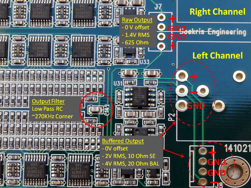
C142
Try different cap values there till 10nF
- Home
- Vendor's Bazaar
- Reference DAC Module - Discrete R-2R Sign Magnitude 24 bit 384 KHz