Hi,
I'm working on a high power amplifier. I will use Vishay PB5008 rectifier, which is PCB mounted version. My question is the cooling.
Most of the high current rectifier is the usual square metal case version, with 6.3mm connectors. And these are mainly fixed on the box of the amplifier.
The PB5008 is designed to attach to heatsink. I found some solution using small attachable aluminium heatsinks. This solutions looks weak to me, as the datasheet define the dissipation, which can be up to 80-100W with high current.
Is there anybody who use this type of rectifier? How to cool it? Is the small heatsink is enough?
Thanks:Sajti
"High power amplifier" - how high? I would say that any more than 200W into 4 ohms and you need to be using either low Vf diodes or a case-mounted block to get rid of the heat.
"High power amplifier" - how high? I would say that any more than 200W into 4 ohms and you need to be using either low Vf diodes or a case-mounted block to get rid of the heat.
It will be 2x600W/4ohm.
Sajti
That means the rectifier will be dissipating about 12Watts at full load.
Hardly worth worrying about. A 12W/degree heat sink will keep it well below 70C.
Hardly worth worrying about. A 12W/degree heat sink will keep it well below 70C.
I'd say it's more like 20W or so power lost on the rectifier, that is not negligible, at that power the case still can safely reach a high enough temperature without fail ( according to it's datasheet ), still it needs a good heatsink, 20W are not very easy to get rid of. I think it would be better to mount it on the amplifier case and connect it with wires to the board, because fitting an heatsink capable to dissipate 20W on the board may not be easy or even possible.
That means the rectifier will be dissipating about 12Watts at full load.
Hardly worth worrying about. A 12W/degree heat sink will keep it well below 70C.
Hi,
the datasheet shows about 40W dissipation for 22A rectified current. It needs about 0.8K/W heatsink to dissipate.
Sajti
I think it would be better to mount it on the amplifier case and connect it with wires to the board, because fitting an heatsink capable to dissipate 20W on the board may not be easy or even possible.
I want to avoid it, as I choose this rectifier to reduce the internal cabling in the amplifier.
Sajti
Last edited:
For 600W onto 4 Ohms you would have about 11A for both channels, so about 20W of power loss on the rectifier. As for what size of a heatsink is needed and what can be fitted on to the board, they may be 2 different things, it depends on your supply board, it's layout and size. You could design it as so the rectifier bridge gets positioned on the side, so you can actually fix it on the case or on some big enough heatsink.
For 600W onto 4 Ohms you would have about 11A for both channels,
That is true, sorry it was my mistake with the calculation.
Sajti
No problem, everyone makes mistakes at some point...
Do you already have the supply board fitted, or it is still on the drawing board?
Do you already have the supply board fitted, or it is still on the drawing board?
No problem, everyone makes mistakes at some point...
Do you already have the supply board fitted, or it is still on the drawing board?
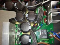
I have the first version of the board. However I found one interesting picture.
4kW amplifier using same rectifiers, with very small cooling....
Sajti
Attachments
Then you have to come up with a way to accomodate quite a big heat sink on your PCB for the bridge.
Bear in mind that a failed bridge will take out the bulk capacitors and possibly damage the amp too!
edit: just seen last post with photo. They seem to be using dual secondary PSU scheme, this will reduce load on bridge, but still I think they are risking it long term... And that 2kw they quote is probably very short term only, if even a real rating.
Last edited:
They seem to be using dual secondary PSU scheme, this will reduce load on bridge, but still I think they are risking it long term... And that 2kw they quote is probably very short term only, if even a real rating.
Almost. It's class H amplifier, one rectifier for low rails, and another for high rails.
Of course it reduce the dissipation of each rectifier.
Sajti
I also think it is risky on the long run, the heatsinks there are too small.
Can you show us your version of the power board?
Can you show us your version of the power board?
Last edited:
Can you show us your version of the power board?
Attachments
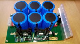
Thanks for sharing, it looks very good, and as i sugested, the rectifier is positioned very nice, i think you could fit there just about any heatsink you like, i think it should be a bit bigger than that one, it is easy because the board's layout permits it.
Thanks for sharing, it looks very good, and as i sugested, the rectifier is positioned very nice, i think you could fit there just about any heatsink you like, i think it should be a bit bigger than that one, it is easy because the board's layout permits it.
The existing heatsink is 4K/W, and maybe not big enough. And I plan some improvement, using thermal switch on this heatsink to save the rectifier.
I used the common method with fixing the rectifier on the wall of the chassis.
Sajti
Heat dissipation is directly related to AVERAGE power.
For a ClassAB or ClassD or ClassG/H the AVERAGE current through the PSU can be very low, even when reproducing at high levels. GlassG/H require the AVERAGE to be low otherwise the amplifiers would fail due to overheating.
I have generally bolted the square block type bridge rectifier to the floor of my amplifiers.
The To220 type usually stay cold/cool without a heat sink or in exceptional builds may require a 30C/W sink to each. The Vf drops as temperature goes up.
But ClassA or very high bias ClassAB is different.
Here AVERAGE current through the rectifiers can be at a sufficiently high and continuous level that rectifiers can become hot.
I had a single channel of Krell KSA100 Klone on quiescent test (no Chassis). Dual bridge rectifiers from dual 37Vac secondaries. I touched the rectifier case and nearly got burnt.
Attached one 7.5C/W sink to cool BOTH bridge rectifiers.
Now the rectifiers hardly got warm, I'd guess <40ºC, but this was with a bias current of 2.7Adc continuous.
- Status
- Not open for further replies.
- Home
- Amplifiers
- Power Supplies
- Cooling of bridge rectifier