Member
Joined 2006
BGs take a couple of hundred hours to burn in I think..
Oh..you are right..those are dip8 chips and so are not opa861s then?...
Oh..you are right..those are dip8 chips and so are not opa861s then?...
Member
Joined 2006
Going back to that photo in the link, my educational guess is that its an opa660 OTA doing the I/V conversion, then to a high impedance ccs'd FET, followed by the high input current buffer inside another opa660...
Member
Joined 2006
Edited:
Going back to that photo in the link, my educational guess is that its the OTA in an opa660 doing the I/V conversion job, then output to a high impedance ccs'd FET, followed by a volt buffer (with higher input bias current) inside another opa660 (or other dip 8 buffer) to provide the dac output ..
Going back to that photo in the link, my educational guess is that its the OTA in an opa660 doing the I/V conversion job, then output to a high impedance ccs'd FET, followed by a volt buffer (with higher input bias current) inside another opa660 (or other dip 8 buffer) to provide the dac output ..
Hi, you guess it's an opa 660 dip 8 package or you read it on the top of it ?
The I/V is passive with a resistor, the oap is here to amplify the small output current of the TDA1541 before the passive voltage conversion, at least this is my understanding. For me this big dip oap can only be two things : an output buffer after the i/v or an element of the diamond buffer first stage involved before the I/V (just after the dac chip)
Because Audial always uses opa 861 in small package and this is also my understanding it uses only one in the Audial S (if I find a job, this would be my first bug buy !) for the I/V stage as the AYA 2 but the buffer is an improved one despite a second 861 !
If you open it, you will see certainly the Black Gate as well for the dac chip powerstage! little blue are the NX, reds are the N serie ! you will se also the N serie as DC stopper as you have not the output traffo version !
I'm really happy with my AYA 2 2014, the trade offs P. choosed makes senses to me and are pleasant to the ears... 16/44.1 sounds fine !
Member
Joined 2006
I never opened it. After you pointed out the package difference, then I started googling for the info..as I am interested in putting together an output stage based on opa OTA for a 9018 dac at the moment....
Pleasant sounding is a good description, in the past I would skip tracks very frequently with the remote, but not any more... 🙂
Pleasant sounding is a good description, in the past I would skip tracks very frequently with the remote, but not any more... 🙂
Last edited:
It sounds strange to me a diyer is not interested by opening him Model S.
Ah, if so let me know if the BG and 660 are always on the party 🙂
Ah, if so let me know if the BG and 660 are always on the party 🙂
Member
Joined 2006
I was late for the full BG version party, so mine has some e-caps replaced by BG Nx in the super e configuration in the analog section only, for an extra cost..
Not only I am lazy, but also lack of any hex tool to do it....😀
Not only I am lazy, but also lack of any hex tool to do it....😀
Member
Joined 2006
Please understand that was a pure guess on the opa660, reason being thats a dip8 while others are not...
Hi
I have a problem with the negative power supply for the opa861 op amps, there is a short circuit across q402 and C403 resulting in no negative power supply for the op amps. All the components are in the correct places and are the correct components.all other power supplies check out ok. thanks if someone could give some advice. (have posted pic scans on Audial blog)
I have a problem with the negative power supply for the opa861 op amps, there is a short circuit across q402 and C403 resulting in no negative power supply for the op amps. All the components are in the correct places and are the correct components.all other power supplies check out ok. thanks if someone could give some advice. (have posted pic scans on Audial blog)
Last edited:
Hi Peterma,
Pedja Rogic would help you. Ceratainly an error of populating (I did also !) !
First check if you have the correct voltage at all the analogs rails at the pins of the 100 uF last decoupling caps !
Hurry up ! Since I finished it : I'm in an intensive listening phase and I'm happy with this DAC : https://www.youtube.com/watch?v=68mbWDKXhiU (looks like how I'm in my living room with the AYA 2 2014 😀)
"Music 'is good for your soul" !
Thanks Pedja !
Hi had a listen this weekend and very happy with the sound, only trouble for me is i have so many transformers to power it 6x9v and 1 x18v It would be nice to buy the original aya trany looking back now I should have! wonder if pedja has any spare?
Has any one tried the external clocking for the DEM circuit? I wonder if it sounds better then the simple capacitor? http://www.audialonline.com/online-topics/aya-ii-2014-diy-edition-second-run/
Last edited:
@Peter:
maybe here:
--> http://www.diyaudio.com/forums/swap...2014-pcb-ei-transformers-power-isolation.html
maybe here:
--> http://www.diyaudio.com/forums/swap...2014-pcb-ei-transformers-power-isolation.html
Has any one tried the external clocking for the DEM circuit? I wonder if it sounds better then the simple capacitor?
My understanding is Pedja uses it on the Model S.
I test the TDA1541 non A, so without dem sync cap ! Odd result : medium is better but I need more listenings ! But I find the low end dull vs a A chip !
Maybe because pin 4 is buzy with the simultaneous mode ? I don't know.
Lukas Fikus said the non A rocks more... not the sample I have in simultaneous mode, in fact it is sweater with a more relaxed medium which is even more clear though having some thick an mate backstage... but at the moment a no go because the dull bass !
@ Peterma : did you swap the main cap voltage value (the one of the BOM) of the -15V rail because your 18V traffo ?
Last edited:
Member
Joined 2006
I had those last months several PM for the same askings !
Time to ask Pedja Rogic for a third run ?
The layout is more than good and enough, there are uf-l connectors for both I2S or simultanous mode ! (choose the USB, IanCanada stuffs you want before 🙂 ).
The I/V stage is still the best with solid-state... and the power supply dac section with independant lines is smart and not a bad gaz-factory as we can see elswhere here with common impedance !
And the building thread on Audial allow the main building issues (frankly there are none 🙂 )....
Last edited:
I test the TDA1541 non A, so without dem sync cap ! Odd result : medium is better but I need more listenings ! But I find the low end dull vs a A chip !
Maybe because pin 4 is buzy with the simultaneous mode ? I don't know.
Lukas Fikus said the non A rocks more... not the sample I have in simultaneous mode, in fact it is sweater with a more relaxed medium which is even more clear though having some thick an mate backstage... but at the moment a no go because the dull bass !
I have several non-a chips from Philips players that do have an osc cap of 470 pF (pin16/17); measured higher though. So better include one, to see.
- I had the same result as you regarding bass with non-A, and finding a good value is hard (went up to 560pF)

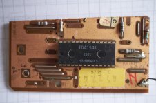
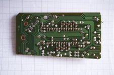
You can clearly see the osc cap. mirrored from the above picture:

- Home
- Group Buys
- GB: AYA II TDA1541A DAC (2014 Edition) PCB or Kit