For that matter, you could make completely new electronics. I've got a nonfuctioning SL-1500 I've wanted to fix and/or make new electronics to drive with an ARM microcontroller. It's amazing what's possible now with cheap electronics, OTOH it's amazing what they did 45 years ago with all those three-terminal devices.
This is something I have been mulling as I have an old Trio/Kenwood DD I would like to redo the electronics for. Sadly Round Tuits are on several years back order at the moment 🙁 Steerpikes webpages do give a good introduction to what is needed tho.
In case anyone needs a brake assembly for their table: Technics SP 10 MK2 Motor Break Assembly | eBay
Not mine, no affiliation.
Not mine, no affiliation.
I was looking at his offerings a couple of days ago. he does have a whole one as well £350 (so about $500) for a 'faulty' unit with no PSU. I guess like many things tho worth more as parts. I realised how much it would cost to even get one up and running close to stock, and decided, maybe next decade.
We'll see. I wouldn't mind some spare parts, but not at those prices. There haven't been many SP-10 listed lately, but six months ago it wasn't at all difficult to get one in unknown/not working condition without power supply for around $300.
Mr. Cawley et al,
In an earlier post you said to look for approximately 2Vpp on the motor drive. I'm getting 3Vpp on 33. Any concerns?

In an earlier post you said to look for approximately 2Vpp on the motor drive. I'm getting 3Vpp on 33. Any concerns?
Attachments
Last edited:
I have questions, if I may. What happens if there's an increase in load on the platter, such as a stylus in a groove, or something larger such as a light finger touch on the rim? (I'm thinking a small paint brush might make a decent "drag standard")Mr. Cawley et al,
In an earlier post you said to look for approximately 2Vpp on the motor drive. I'm getting 3Vpp on 33. Any concerns?
Does the voltage go up? Does the phase or frequency change at all (and can you see that with the sync based on something that also changes)? The electronics clearly "does something" to compensate for an increased load, and I wonder exactly what it is.
3V is OK, but have you changed the three 10uF on the output of the motor drivers ?
Ben, yes the voltage will increase but the frequency does not. The phase may delay but will recover when the load is removed. This is one of the reasons why Technics MKII turntables have such wonderful timing.
Ben, yes the voltage will increase but the frequency does not. The phase may delay but will recover when the load is removed. This is one of the reasons why Technics MKII turntables have such wonderful timing.
Yes, all electrolytics have been replaced and the PLL readjusted.
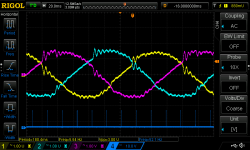
Ben - In this video, the fist four amplitude increases are me dragging my finger on the platter, and the latter are me applying pressure far beyond what would easily stop a belt or idler drive. This video is me tapping the table while suspended.
Ben - In this video, the fist four amplitude increases are me dragging my finger on the platter, and the latter are me applying pressure far beyond what would easily stop a belt or idler drive. This video is me tapping the table while suspended.
That's fascinating, guys. thanks for the responses. The operation appears to be pretty much what I described in this post a few years back:
http://www.diyaudio.com/forums/analogue-source/71356-why-dd-bad-4.html#post2219981
Rewriting a little bit to what I "really meant," the drive coil SIGNAL CURRENTS should be some fixed phase ahead of the permanent magnet poles, so the coils are always "pulling" the platter. A good, quick detection of speed decrease (caused by an increased load) allows for a virtually instant increase in drive force to correct it without any change in drive frequency or phase.
The three sense coils go to a three-phase rectifier circuit (it looks just like the diodes in a car alternator!) to generate a voltage proportional to the platter speed. I somewhat recall discussion earlier in the thread on this, and that the (needed) filtering of this rectified voltage gives a delay that is, of course, undesirable inside the speed control loop. I'm frankly amazed this analog speed detection circuit works as well as it does using the relatively low frequency signal (is the sense frequency 5 Hz at 33rpm, just like the drive frquency appears to be in #606?).
Are there any patents related to this design? Do any other DD turntables operate this way?
Ben
Some of what you say is loosely correct but with several fundamental errors. Please read my published article on Direct Drive and the SP-10 MKII service manual.
Regards
Dave
Some of what you say is loosely correct but with several fundamental errors. Please read my published article on Direct Drive and the SP-10 MKII service manual.
Regards
Dave
Dave, perhaps you've already published a link to these published articles somewhere in the 612 posts on this thread, but could you re-post them for the benefit of folks who may have arrived late to this party?
thanks
thanks
I don't know what I was thinking in my last post, I clearly forgot half the circuitry, such as a PLL, but whatever.
But I was prompted to look through my files. I downloaded the following PDFs a few weeks ago as I was saving and reading through this thread and other SP-10 related things, but I totally forgot where I found the files, if they were mentioned in a diyaudio thread or what, but searching for them in my web browsing history brought up the URL sources.
These are explanations of various aspects of SP-10 operation and control loop(s):
http://web.eject.co.za/s8nspawn/sp10web/sp10loop.pdf
http://web.eject.co.za/s8nspawn/sp10web/sp10pllg.pdf
http://web.eject.co.za/s8nspawn/sp10web/sp10the.pdf
Actually those are not necessarily the SP10 control loops, but an implementation to control an SP10 motor. But the theory is good.
.
+1 !
Actually those are not necessarily the SP10 control loops,
+1 !
So has everyone given up on the "new improved" platter? Are plans available? We have a machine shop here in Hawaii that does aerospace work that probably could produce.
Anyone else have any updates to their builds? Hard to learn anything new if nobody speaks!
I have been spending some time learning the adjustments for my 312S arm. Still using my $100 Ortofon Red cart for practice. Since this is my first turntable I don't know any better, but I can tell improvements as I dial in the arm/cart. Just ordered an Andonstar 2 MP USB Digital Microscope Camera to really dial in a cart.
Im practicing for my real cart, but I'm not yet comfortable to install yet. Need to be sure I understand everything I'm doing and why. And above all, make sure I know how to to install and adjust without causing damage.
My real cart is a Koetsu Urushi Black (black to match my arm).

So it sits in its cute little box till I feel ready. Maybe late next week after I have some time figuring out how to work the camera and adjust the VTA. It is really beautiful though!
Anyone else have any updates to their builds? Hard to learn anything new if nobody speaks!
I have been spending some time learning the adjustments for my 312S arm. Still using my $100 Ortofon Red cart for practice. Since this is my first turntable I don't know any better, but I can tell improvements as I dial in the arm/cart. Just ordered an Andonstar 2 MP USB Digital Microscope Camera to really dial in a cart.
Im practicing for my real cart, but I'm not yet comfortable to install yet. Need to be sure I understand everything I'm doing and why. And above all, make sure I know how to to install and adjust without causing damage.
My real cart is a Koetsu Urushi Black (black to match my arm).
So it sits in its cute little box till I feel ready. Maybe late next week after I have some time figuring out how to work the camera and adjust the VTA. It is really beautiful though!
I would still up-front on 10 units and sell at cost to diyaudio members (of 6 months standing) 🙂
- Home
- Source & Line
- Analogue Source
- The Incredible Technics SP-10 Thread