Farnell stocks the Sharp GP1FAV31RK0F optical receiver (15.5 Mb/s). Works fine, but I don't know about 192kHz.Just to complete the confusion Mouser did actually sell a part called TORX147PL(25M,F,T)
Not sure what the 25M imply as specification and datasheet connected for this item still list 15Mbps.
The PL notation I’ve found are the version with shutter. L version have dummy plug.
TORX147PL(25M,F,T) Toshiba | Mouser
Not sure if anyone have searched for TORX147 over at AliExpress? Lots of hits. Most of them obvious scams. Or used parts painted and tinned. One seller didn’t even bother to use fake pictures, but posted images of the AX device I probably would get in the mail.
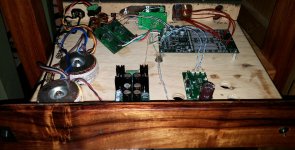
Yet another attempt to "see" the effect of PSU on DAM1021
Last night, I assembled 2 Salas BiB +12V regs and connected them to give +/-12V to DAM1021. The regs were assembled by using parts suggested by Salas/Teabag, except I replaced the unobtanium toshiba jfets by CRD.
The motivation for attempting BiB as PSU for DAM is simple: I find DAM lack in punch and authority although it gives extremely transparent and detail sound. The timbres (classical music playback) reproduced through DAM1021 are extremely realistic.
Here are the main differences between using a Nuvotem 7VAC x 2 (7VA) and a (pair of) BiB shunt reg:
1. BiB shunt reg extends the soundstage to left/right slightly but extend its depth;
There is no big difference in the width of soundstage but the depth is quite different. And the background is very quiet (dark) with BiB shunt reg.
2. BiB shunt reg helps to reproduce the low frequency region better;
It reproduces the dynamic and atmosphere of Eva Cassidy Live CD. Blechacz's Polanaise has more authority and weight now, yet not enough for me.
3. Most importantly, BiB shunt reg provides excellent separation of instruments and pin-sharp imaging.
I listened to Thomanerchor/Gewnadhause Mozart Requiem several times during the Easter Holiday. When the BiB shunt is used, the distinct position of each vocal section is reproduced in a pin-sharp manner. While playing Mullova/Ozawa Tchaikovsky Violin Concerto/ Rostropovich Haydn Cello Concertos, the orchestra are clearly behind the soloists.
In short, the imaging is extremely holographic.
Here are some thoughts or further investigation/possibilities:
1. desolder and by-pass the bridge rectifier after J1?
2. Or, simply connect the BiB shunt regs to PWR+ / PWR - in J2?
3. remove the L1 in Amanero USB-I2S and supply it with an external PSU?
Any comments or idea ?
Note:
Here are my set up -
Synology 214 ==> Amanero ==> DAM1021 ==> Passlab Aleph L ==> Aleph 3 ==> Audio Physics Tempo 25.
When giving sound impressions, please state the used filter.
//
Thank you for the reminder, TNT.
I am using TotalCRAP at the moment.
I also replaced a transformer with a dc ps. I used a tiTPS7A3001 and TPS7A4901 . I use the stock firmware. I also moved the dam into a koa wood case with 2 TPA teleporters, an Otto 2, a bnc and soon a toslink. So 2 i2s inputs along with the bnc and optical. The good dc input opened things up. Sounds very precise and clean. Now waiting for the new nichicon fw caps to settle.
Attachments
I find DAM lack in punch and authority although it gives extremely transparent and detail sound.
The TotalCRaP filter will do exactly what you describe. It will make low level information appear more prominent relative to louder events. This makes the TotalCRaP filter sound very detailed but reduces the dynamics and makes recordings sound flat.
I actually think it is a pretty unbalanced filter and would not recommend using it. Filter brewing been a pretty steep learning curve so newer is better with the filters. The NQ series filters are currently my SOTA. I'm working on tuning the tonal balance so user feedback would be useful.
XLR Connectors distance / gap?
Hi all,
I'm making a back panel in Front Panel Designer for the PCB mount XLR chassis connectors. What is the distance between the L / R connectors? Sorry I couldn't measure it myself because I haven't got the DAC yet, but I need to send the DXF files to the CNC guy very soon. Thanks!
Hi all,
I'm making a back panel in Front Panel Designer for the PCB mount XLR chassis connectors. What is the distance between the L / R connectors? Sorry I couldn't measure it myself because I haven't got the DAC yet, but I need to send the DXF files to the CNC guy very soon. Thanks!
Hi all,
I'm making a back panel in Front Panel Designer for the PCB mount XLR chassis connectors. What is the distance between the L / R connectors? Sorry I couldn't measure it myself because I haven't got the DAC yet, but I need to send the DXF files to the CNC guy very soon. Thanks!
Center-to-center distance between the two XLRs on the board is 1.20 inches.
FWIW, if you're not bent on metal (pardon the horrible pun) I have sent PDFs generated at 100% scale by Front Panel Designer to a trophy engraver who produces perfect Perspex panels (entire enclosure, limited only by your imagination) for a fraction of the cost of FPD. Including all lettering, logo etc. Their CNC laser machine can handle up to 3/16" Perspex - which you supply. And it's local so no shipping, turnaround usually 24 hours!
Last edited:
Waterjet also works
The trophy shop idea is great!
I also used FPE tool to design my project. Then exported the design to a standard file format and sent it to some local shops for a quote. A waterjet shop produced a reasonable quote which I could pick up without the shipping or customs clearance fees. Waterjet can cut anything from metal to marble. I think Front Panel is great, but being in a different country, a recent small job quoted at $15. By the time I paid shipping, USD conversion and then import fees to the UPS guy I had shelled out $75. Just was not worth it.
Hi all. I have not implemented the dac in a "Box" yet. (I have a nice primare T20 tuner case I would like to use) - but I implemented a remote volume control quite ease the other day.
I was fortunate to have an alps rk168 (20kohm linear) motorized potentiometer taken from an old pioneer pds602 cd player laying around. The excact pot # I will check.
I bought from ebay a remote control kit like this:
Remote Power on Off and Remote Control Volume Board | eBay
I then changed the 100kohm potentiometer from ebay kit to my 20kohm alps.
To get 10kohm from the 20kohm I parallelled the stereo pot so I could get 10k mono pot.
The setup before I will put it in a case is like this. 🙂 some parts 🙂
https://docs.google.com/file/d/0B6y-cEFCiv7TZmV3TjhzSkZsNDA/edit
Wo
Using regulated PS
I tried a number of times by switching between regulated power supply and connect directly to a 2x9V transformer before it died.
The regulated PS is a 317/337 configuration and the +ve rail draws so much current that the head sink for 317 turns 85 degree C after 5 minutes. I have to replace the heat sink with a bigger one to maintain its temperature to 70 degree C. There is a 3.3V regulator on board that draws current from the +ve rail that I THINK if we supply this regulator with a separate and lower DC voltage, this will reduce the current draw from the main +ve rail. Besides, this will also help to reduce the heat of this 3.3V regulator because it is not necessary to drop the voltage from the main supply to 3.3V.
The background is darker with regulated PS thus reflecting more details and the high is getting more "crispy". However, it is dead now and I am waiting for anyone to provide their ideas on how to repair it.
Last edited:
You should be using 7-8V AC transformers... even then only your capacitors may be stressed and possibly damaged but for the rest of the components to die is sort of odd.
Have you tried to measure all the voltages from J2, yet?
Have you tried to measure all the voltages from J2, yet?
It also is very odd that the board seems to draw that much power. Heating up the LM317 might be an indication of something being wrong elsewhere... even in the supply.
I am powering my DAM with a simple LM317/337 supply as well... no hickups and heatsinks just barely warm to the touch (which should be expected with the low current draw of the board).
I am powering my DAM with a simple LM317/337 supply as well... no hickups and heatsinks just barely warm to the touch (which should be expected with the low current draw of the board).
Hi Ristar, I measured all voltages from J2, every point is normal except the 3.3V turns out to be 2V only.
Does it really matters by using 9V AC supply? 9V AC after regulation is only about 12.6V DC while capacitors are rated at 16V.
Hi Stixx, I forgot to mention that the transformer being used for the 317/337 regulator is having 18V AC as I don't have a 14 or 15V AC transformer on hand.
Does it really matters by using 9V AC supply? 9V AC after regulation is only about 12.6V DC while capacitors are rated at 16V.
Hi Stixx, I forgot to mention that the transformer being used for the 317/337 regulator is having 18V AC as I don't have a 14 or 15V AC transformer on hand.
Well your regulator seems to be dealing with a lot - which will cause problems. RE: 9V AC... in a perfect world you won't have a problem... as you've already experienced... turning things on will sometimes cause that value to be exceeded. This is the reason Soren recommended 7-8V AC even though the board can theoretically handle up to 16v DC.
EDIT: The 3.3v LDO is ZLDO1117... you can replace that or use a better spec'd one like a TPS7A4700 which some have done... I'm using ADM7150
EDIT: The 3.3v LDO is ZLDO1117... you can replace that or use a better spec'd one like a TPS7A4700 which some have done... I'm using ADM7150
Last edited:
I already replaced the ZLDO1117 3.3 with a new one but the output voltage remains 2V. In fact, I checked the old ZLDO1117 on an external circuit, it is working perfectly. This is why I think there must be a damaged spare part somewhere that I have to trouble shoot it out.
It's drawing too much current. One of the parts the 3.3V reg is supplying is faulty, or is driving a short.
Trying lifting the voltage pin on a chip that receives 3.3V, and see if the output of the 3.3V LDO goes back to where it should be.
Don't be concerned with other changes until this is fixed.
Trying lifting the voltage pin on a chip that receives 3.3V, and see if the output of the 3.3V LDO goes back to where it should be.
Don't be concerned with other changes until this is fixed.
Ouch... quite a number of components use that rail... clock, fpga, RS232 chip, clean side of isolators.
I guess the easiest check is getting a usb to rs232 serial (not TTL-level) to see if you can connect to the fpga. Then also check if it changes sample rate and locks...
I think someone else killed the isolators by applying the wrong voltage in this or the main thread - I'm not sure if he/she managed to replace it.
- Home
- Source & Line
- Digital Line Level
- Soekris' DAC implementations