The TSSA V4 is still more power full and can work with higher rails.
The V4 will have 4 pairs of single die mosfets with an max working voltage of +/-55VDC. Current capability of this one will be 24A peak (I am on the safe side here) which will make it run into 2 Ohms load while still nearly doubling it output power over 4 Ohms load.
TSSA V2 will have 3 pairs of single die mosfets with an max working voltage of +/-45VDC. Current capability of this one will be 18A peak (I am on the safe side here)
Not as powerfull as the TSSA V4, but with exotic parts in the right places.
The TSSA V2 will be just an finetuning of the TSSA V1.8... To get the last drop out of it....
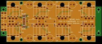
Bottom layer Schematics with remarks.
See the attached PDF. As you all can see, it is laid out for 4 pairs of mosfets of the double die type.
Protection is done with an transistor instead of an Zener diode as they have less parasitic capacitance.
Each mosfet will have a source resistor of 0.25Ohm and 8W. This will give an rms value of 5.6Arms per mosfet. But every mosfet is only driving an half wave sine it will be equalent to about 10Arms per mosfet.
So basicly the current capacity will be 40Arms, if the mosfet allows it... More than plenty.
Every mosfet will have an yfs of 2S (including the source resistor). but we have 4 pairs , so compared with the TSSA V1.8 which has 3.33S, the TSSA V4 will have an yfs of 8S. So that is an win-win.
The input stage will be mounted on top of the output stage. There was no room for it on the board for the output stage.
The design allow an 40VAC secondary on the transformer or 60VDC.
The output stage is open drain configuration. So the worst voltage drop across the mosfets are 10VDC. this gives us 50Vpeak or 35Vrms.
So a quick calculation should gives us no current drop... Not even into 1R Load. => 1200Watt into 1R.
Sorry, it takes that long time. But this will be a serious upgrade.
Attachments
Received yesterday the new caps Sonny send me and put hem on ASAP.
Initial impressions seem to be very positive and I think that these caps take the TSSA to new level of resolution and refinement. I haven' t done much listening and I won' t have a lot of time free until next week, but I think that they are staying on my system. Let them burn in a few hours more and next week sometime maybe will be able to say more.
As you may have noticed, I do not use the bypass caps (tried them, liked the sound without them) and previous caps tested were Panasonic and Nichicon FG.
Also the amp is biased on 1 amp and I use it from around 90 Hz with fairly sensitive speakers.
Attachments
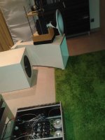
From the caps report I wonder what one may think when reading "fairly sensitive speakers" and then looking at the second picture.😀
Most amps would drown the Music In background noise on those speakers.
Sent from my iPhone using Tapatalk
Sent from my iPhone using Tapatalk
From the caps report I wonder what one may think when reading "fairly sensitive speakers" and then looking at the second picture.😀
More than 105dB now..... really like it 🙂
Finally got around to swapping out Elco's and removing bypass caps. IMO, a highly recommended changes. IMO, it gives the impression of greater clarity and resolution, especially in the midbass/lower midrange. This was a noticeable area of comparison vs my Pass clones. Unifrtunately I was not able to compare FG vs organic polymer, as I went straight to the polymer.
Will be taking it over to listen on another system tonight.
Will be taking it over to listen on another system tonight.
I have found out that würth also has polymer types with equally low esr of 8mohm. But they have values as high as 2000uF.
But i have not testet them yet.
But i have not testet them yet.
In another amp, I tried both Nichicon and Panasonic version of the polymer caps, neither showing a great difference. I think the benefits are a result of the physical construction of these vs traditional aluminum Elco's.
In another amp, I tried both Nichicon and Panasonic version of the polymer caps, neither showing a great difference. I think the benefits are a result of the physical construction of these vs traditional aluminum Elco's.
In which position were they? In the feedback loop also?
My comparison amps are F6, J2, symmetrical F6, and soon, an XA.8 clone.
Preamp is XP clone, LSK, and soon, a rebuilt Salas 6v6.
Sondek TT, Sota Sapphire, and Throens Td850.
Cartridges are Ortofon Kontrapubkt B, Rhondo Bronze, Sumiko celebration pear wood, Dynavesctor 20x2
Riaa are Salas, and PS audio
Speakers are couple home brew jobs, variation of Kalasan bookshelf, Maggie's, and small Ariel floorstanders.
I generally try to vet stuff in multiple settings and with multiple ears.
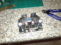
The TSSA V4 powerboard is now completed.
It is shared between TSSA V4 and V8.
The difference is the type of mosfet mounted.
TSSA V4 will have an current capacity of 25A peak. This will make it "double" its power every time the load is half ed down to 2Ohm load.
The same board with double die mosfet will be around 45 - 50A peak.
The boards is equipped with polymer caps. No film capacitors is parallel here.
Later today i will post picture of the amplifier board that is mounted on top of the powerboard.
The TSSA V4 and TSSA V8 is essentially the same, but differences are the polymer caps with higher voltage rating, the double die mosfets.
The TSSA V4 will be mounted with 63V capacitors meaning an maximum voltage of around 55Vdc
The TSSA V8 will be mounted with capacitors of 80V meaning an maximum voltage of around 70Vdc.
They both covers the voltage downwards to around 35Vdc.
They both have balanced inputs.
TSSA V4 will cost 314€/per channel. + shipping
TSSA V8 will cost 449€/per channel. + shipping
i will do a trade in for old modules -> discount of 40€/channel (only one module in tradein for one new module)
Attachments
Looks great Sonny!
What's the confirmed power output @ 8Ohm for V4 and V8?
Any early bird and/or volume discount planned.
What's the confirmed power output @ 8Ohm for V4 and V8?
Any early bird and/or volume discount planned.
To do any price calculation on groupbuy i need to know how many is interested. I will also calculate an price for early bird. Let me know.
The PCB is in production.
The PCB is in production.
- Home
- Vendor's Bazaar
- TSSA V1.7 mosfet Current feedback amp module