Indeed, jneutron, I think you and I are the last men left standing on this topic. 😀As I said, read the posts. Don't be afraid..
jn
How we laughed when the learned Professor Laithwaite made an *** of himself on gyroscopes and anti-gravity! It's like the Pope slipping on a banana skin. Rudimentary methods might still save the day we console ourselves...except they DON'T!
Gyroscopes are extremely tricky things to think about. Why? Because our notions of rotation and angular momentum are still firmly steeped in three dimensions and about an axis. The reality is that rotation is not around an axis, but around a plane, which is entirely different:
https://www.youtube.com/watch?v=q5Qh2XpoCsY
It looks different in 4 dimensions, doesn't it? 😎
I get criticised for confusing your small brains with so many diverse topics in mathematics. But actually maths is EVERYTHING and all INTERRELATED.
Here's a summary of Cable-Lifters. Our current speaker cables have no real design. The best we can do is get the conductors close to reduce characteristic Impedance to near 50 ohms. Then maybe we don't need cable lifters!
Twisted Pair | Electronics and Electrical Engineering Tools | EEWeb Community
We might as well use multi-stranded to maintain flexibility. We could Litz-wire or parallel to get lower impedance, but I think 50 ohms is near enough.
We must then put 10 ohm Zobels at either end of the cable. 10R plus 0.1uF is standard at amp outputs. The same at the speaker filter would be good. The much vilified but precise Transmission Line theory then tells us that we will only see inductance with a cable terminated lower than characteristic impedance. The Capacitance just goes away! 😱
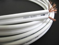
So now you can laugh at Naim's NAC5 cable. It's daft. Must be about 150 ohms Characteristic Impedance. What idiot designed this? What's the arrow supposed to mean? Electron flow?

Attachments

Indeed, jneutron, I think you and I are the last men left standing on this topic. 😀
John must be cringing. 😀
engineering is about tradeoffs - requiring relative magnitude estimates, thresholds, decision criteria
not just "here's an effect you can't disprove" - we often have rational grounds for disregarding effects in some situations/applications that are measurable, even 1st order important in other contexts
not just "here's an effect you can't disprove" - we often have rational grounds for disregarding effects in some situations/applications that are measurable, even 1st order important in other contexts
I have had to improvise "cable lifters" in several engineering measurement applications
one was a 20KHz complex impedance measurement instrument for fluid conductivity - on the megaohm range the prototype's unshielded twisted pair wiring laying on a particle board/linoleum lab bench gave variable and low readings - put the wire, resistance box test load on 4" polyethylene foam blocks and I could get reproducible readings (also had to search out the noninductive cal boxes some were useless for AC, for the megaohm tests I used resistor strings and alligator clip "switching" - even the "good" cal boxes weren't adequate at 20KHz)
in another instance strain gage transducer cable with twisted pairs, overall braid which performed well in every other situation gave large 60 Hz noise on a concrete slab machine shop floor - lifting the cable off the concrete floor dropped the noise by >20 dB
those instances aside - I do believe loudspeaker cable lifters in a domestic environment are pretty silly given source/cable/load impedances - although it is amusing to an engineer that the lowest tier of "Audiophile" cables (Monster) are not twisted (nearly no added cost), "common centroid" 3-wire or star quad configuration but do tout "linear polyethylene dielectric"
Last edited:
Ooops here's the attachment......
Interesting graph, thanks for the effort.
I'm curious, where can I find 100nh per foot parallel pair wire? That is below the inductance per foot that two bare conductors can get to with no insulation gap, conductors just touching. The terman equation here would help.
Also note, you've used a cable which has a characteristic impedance of 90 ohms.
Also, if you go through the numbers, you will find that even in a constrained wire, you have a dielectric coefficient of 1.16. None of this is consistent with a parallel wire pair.
You have modeled a 90 ohm coaxial cable with foam dielectric. AT least the waveforms seem well behaved.
Now, take that simple model, and understanding that we are interested in the response at the single digit microsecond level, use a 200 element model.
Then, consider the fact that the load will vary it's inductance as a consequence of eddy effect, and the effective resistance will also vary due to eddy dissipation.
Then, armed with this new model, include the interaction between the parallel wire cable and the 3.5 inch OD electrical conduit 7 feet long that we have to pull the cable through. You can even model it as 10 meters long on the assumption that we can drill a 3.5 inch ID hole into a 3 foot thick slab of high density concrete with two right angle bends along the length to prevent line of sight access to x rays. Then include the 2 theta modulation of permeability of the metal conduit on the twisted dipole field of the cable, and the eddy losses as well along that 7 feet.
Once you do that, then you need to realize that this line cannot be realized even with a 10 meter run of such high impedance, so look to coax for a solution for impedance as well as external proximity problems.
A quick search of coax finds no low z candidates..high z (50 ohms) still gives us lots of slap, with the subsequent delay.
A quick search of double shielded coax yields a Belden cable, it has a #12awg double shield, perfect for the application. Belden of course, doesn't publish the impedance nor inductance between the double braids, as that isn't what the cable was designed for. In fact, Belden gave up publishing inductance numbers per foot for a lot of their product line years ago..I found that 10% of their catalog inductance numbers were inaccurate.
Now, armed with a double coax suitable for the need, redo all the calcs...voila, success. This cable has sufficiently low z that the cable settling time falls below the application need, either using the t-line app, or lots and lots of cells.
Congrats, you have just gone through all the engineering we did. In 2005.
My moniker, which depicts the magnetic field strength around a double braid shield coax, was put on this site in 2006.
cheers,
jn
Last edited:
Actually, I consider the two people I am discussing this with to be highly intelligent, and I value their opinions. (I may not agree, but still value)Indeed, jneutron, I think you and I are the last men left standing on this topic.
I suspect that you are probably criticised for telling people they have small brains. Perhaps those thoughts are best left at their origin.I get criticised for confusing your small brains with so many diverse topics in mathematics.
We must then put 10 ohm Zobels at either end of the cable.
Putting a zobel of the line impedance at the load should be sufficient. That will keep the line looking at least resistive as the amp approaches it's unity gain open loop frequency. It will also kill any rf that climbs onto the line.
Actually that looks more like the stuff I used to run to the antenna on the roof. Maybe 300 ohm.So now you can laugh at Naim's NAC5 cable. It's daft. Must be about 150 ohms Characteristic Impedance.
If the speaker is well behaved impedance wise, that cable wouldn't be too bad really. It might rolloff a bit on the highs though. If the speaker has wild impedance variations, that cable may not be so good.
jn
Last edited:
I'm afraid there's more to this than that. Material behaviours are part of the story, in fact the major part - altering the materials which are contacting each other does the damage, or "fixes" the sound - the physical layout of wiring is only minutely altered when making these type of adjustments.What you are experiencing is a ground loop. The physical layout of your cordage is trapping magnetic field, and it is being conducted into your equipment. I have absolutely experienced this, but did not use lifters as a solution. Go to my gallery, look at the ground loop drawings.
Overall, there's a complex interplay going on - a whole gaggle of factors are conspiring to drag down the quality of the perceived sound, and every single one of them has to be adequately dealt with to get what one should really be after: sufficiently clean sound.
So now you can laugh at Naim's NAC5 cable. It's daft. Must be about 150 ohms Characteristic Impedance. What idiot designed this? What's the arrow supposed to mean? Electron flow?
I have made exactly these comments in the past....ie re labelled transmitter feeder cable ?.Actually that looks more like the stuff I used to run to the antenna on the roof. Maybe 300 ohm.
If the speaker is well behaved impedance wise, that cable wouldn't be too bad really. It might rolloff a bit on the highs though. If the speaker has wild impedance variations, that cable may not be so good.
jn
The arrows are to help ensure that both channels are routed in the same signal direction...ime this is important.
In practice, Naim amplifiers require inductive cable.
I have tried 10pr IDF cable on a Naim amp and it oscillated.
Dan.
Its trivial to obtain c 100nH/ft from parallel pair wire in various choices of spacing and conductor. You've got it backwards as to what happens when spacing between conductors becomes smaller - inductance drops. This is because mutual inductance increases, and current in each conductor is in opposing direction of course.I'm curious, where can I find 100nh per foot parallel pair wire? That is below the inductance per foot that two bare conductors can get to with no insulation gap, conductors just touching.
You accidentally raise an interesting point that closely separated conductor pairs have lower return inductance. Coincidentally they also have low rf characteristic impedance, and I think this is how you are right in pursuit of low rf Z, but for the wrong reasons, jn. Well you would be right if the cable inductance were large enough and load impedance low enough to produce any notable delay, which is already shown here to be unlikely.
Characteristic impedance is meaningless at audio band for normal cable lengths, for reasons already set out. In any event, 1.5cm spaced 6mm radius zip cord with low dialectric is near the 90R mark at rf for example.jneutron said:Also note, you've used a cable which has a characteristic impedance of 90 ohms.
But it really doesn't matter what the absolute value of the rf characteristic impedance is. Cable inductance/length and resistance/length is all that matters - capacitance is shunted by the output impedance and the load impedance in the audioband, so is irrelevant.
Above the audioband, eg at rf, capacitance might matter if amp output impedance and load impedance rise, and there are consequent stability issues -but that's a different matter from discussion of audio latency arising from cables in which C/length plays a negligible role.
Yes, it's as simple as that ... thrashing around about the cost of doing this in audiophile approved fashion, or delving into the subtleties of transmission line behaviour is completely missing the point ...
No science is stupid as is engineering, way better to make things up and use magic.
The arrows are to help ensure that both channels are routed in the same signal direction...ime this is important.
A.C. signal which way is it flowing?
Nope, TL theory tells us no such thing here. Wavenumber is very small. What the amp 'sees' at audio bandwidth looking into the cable is cable inductance in series with load impedance, shunted by cable capacitance. No matter what the load impedance is. Look it up.The much vilified but precise Transmission Line theory then tells us that we will only see inductance with a cable terminated lower than characteristic impedance.
We all understand that audio is asymmetric AC.The arrows are to help ensure that both channels are routed in the same signal direction...ime this is important.
A.C. signal which way is it flowing?
The point is to ensure that L and R channels are identical....reversing one cable destroys this condition.
Dan.
Hey, it just occurred to me, I have a bunch of old, cheap AR turntable tonearm rests that could be used for lifting cables inside components, speakers or even rca cables!
I might be sitting on a gold mine here, I wonder how many hundreds of dollars I could ask.
I might be sitting on a gold mine here, I wonder how many hundreds of dollars I could ask.
reversing one cable destroys this condition.
Dan.
In what manner?
(This should be cool.)
Stereo playback means two as identical as is possible channels.In what manner?
(This should be cool.)
One reversed cable in the system makes for non-identical channels.
I will not discuss audibility of cable direction here...if you want to by all means start a new thread.
Dan.
Stereo playback means two as identical as is possible channels.
One reversed cable in the system makes for non-identical channels.
I will not discuss audibility of cable direction here...if you want to by all means start a new thread.
Dan.
Right, I'm just looking for the logic behind labeling a channel "non identical". Unless there's an electrical difference in connector wiring, this is one of the more stupid ideas ever put forth in the audio world.
As far as preserving the integrity of this thread's original insipid topic, you can't possibly be serious, after we've entertained literally more than a dozen pages of irrelevant banter about topics with barely a tangential relationship.
I'm sorry if the tone of this sounds like my brow is furled, but it's incredibly frustrating that people continue to drop by just long enough to drop tiny anecdotal statements, and then refuse to back them up with anything except faith based opinion and "one time at band camp" stories.
I think we should be a lot more concerned about the quality of information that's presented when it's labelled as such, so rather than just making a declarative statement and then ducking underneath forum etiquette to avoid having to qualify it, why not just spend an extra few minutes adding something substantiate to an already derailing post.
Right, I'm just looking for the logic behind labeling a channel "non identical". Unless there's an electrical difference in connector wiring, this is one of the more stupid ideas ever put forth in the audio world.
Stupider than cable lifts? I dunno, once you jump into the Stupid Pond, there's a lot of fish swimming around in there.
- Status
- Not open for further replies.
- Home
- Member Areas
- The Lounge
- Speaker Cable lifters or stands?